Already got 2 ways to control it. Why not three.
|
So, I have decided I would like to make my own controller.
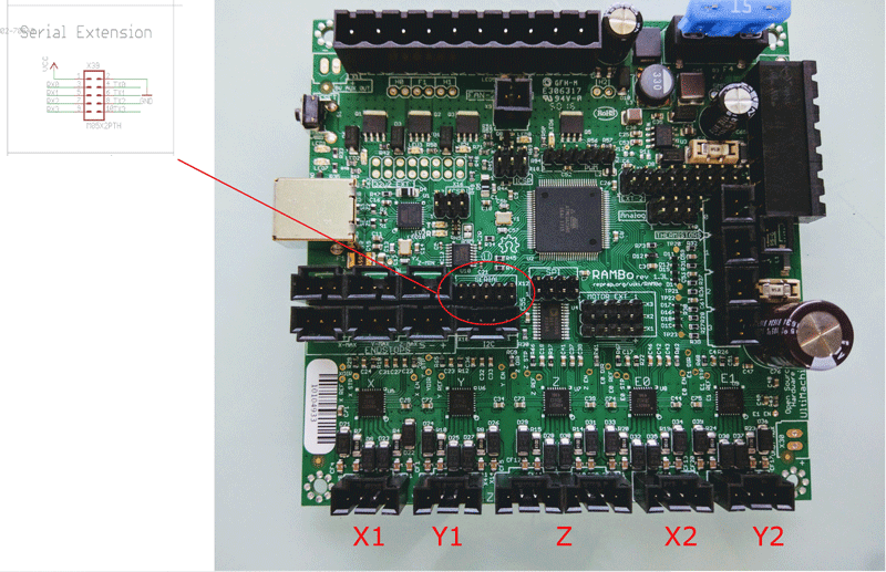
The LCD based one that interfaces with the Rambo CNC controller is pretty horrible to use. Up to this point, I have been using Repetier software to actually control the machine. So, first job. Work out how to connect to the Rambo controller. After the usual Googling, I managed to find out all the connections available on the PCB. Turns out all the serial ports are brought out to a header in the middle of the board. |
You need to go into the Marlin software and enable the second serial port.
This then made the centre 2 pins available for me to communicate with the board, while still allowing the Rambo to talk to my laptop over USB (and therefore use the Repetier software for the actually milling process).
So, lets find some parts.
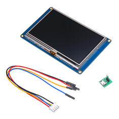
Dug around the workshop and found a Nextion 4.3" touchscreen. Nice.
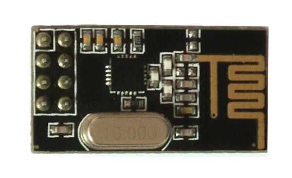
Also dug out a pair of NRF24l01 wireless transceivers, and a couple of Arduino's.
REALLY didn't want to use an Arduino (because I hate them with a passion). but I have loads of them lying around
A Teensy 3.2 would have been nicer, or a Raspberry Pi Zero, but lets use up what we have.
|
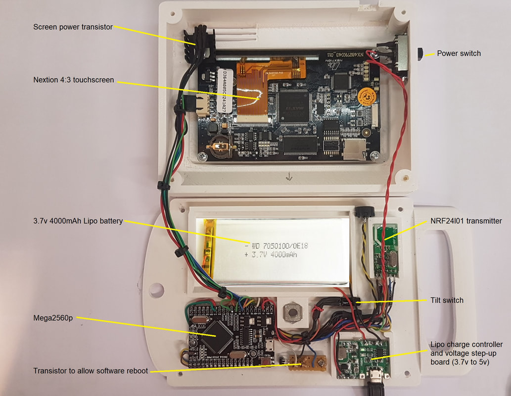
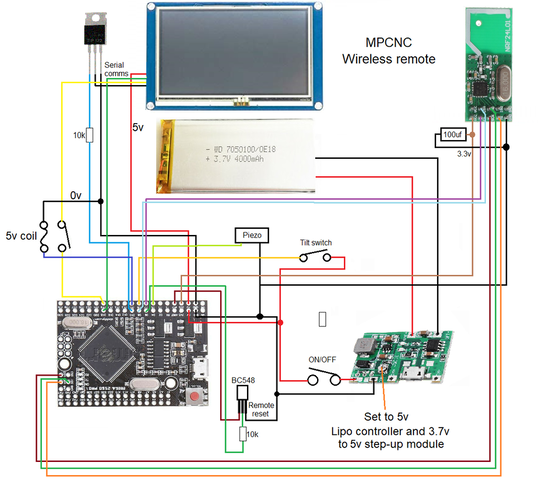
So, I have decided the main 'handset' will consist of :
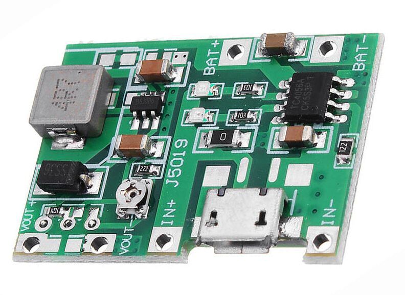
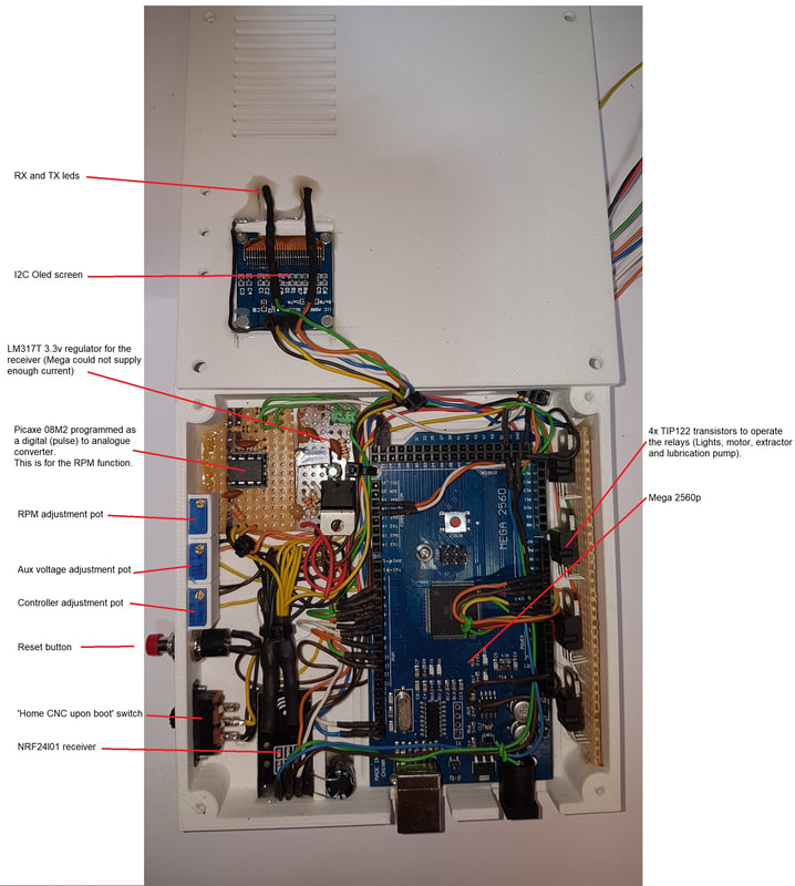
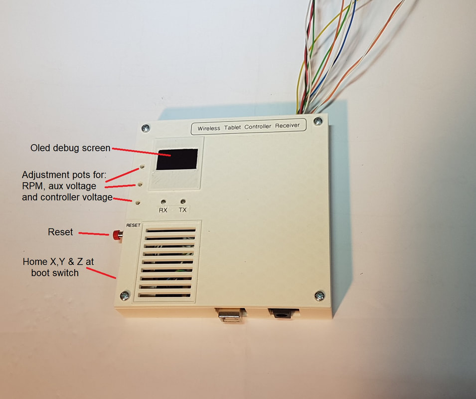
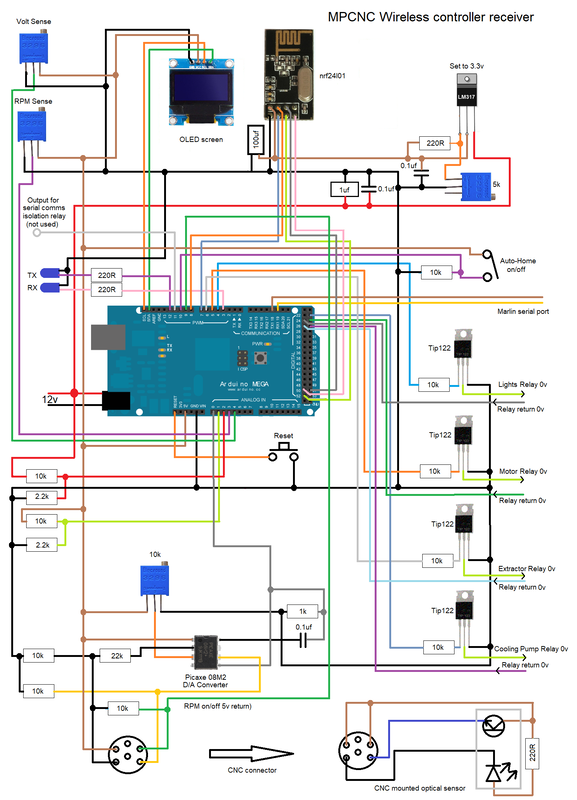
3.7v 4000mAh Lipo + charger circuit A 3.7v to 5v step-up board (also allows the 5v to be supplied by USB while charging the battery). The Nextion touchscreen A NRF24l01 wireless serial transceiver An ATmega2560p IC. This I managed to get on a breakout PCB from China (on dodgy old Ebay), so it is a lot smaller than a standard Arduino Mega2560p board. I will also need a 3.3v regulator for the power hungry NRF24l01 transceiver. The receiver simply uses another Arduino 2560p (Full size), the other NRF24L01 and a small 0.96" Oled I2C screen for debugging. |
So, the first job is to make the Nextion pages.
This is done in Photoshop, or something similar. You need to make the pages in the resolution of your screen. The 4.3" screen is 480 * 272 pixels.
This actually entailed making A LOT of custom buttons. I simply made a template and downloaded a whole pile of free images and assembled my own.
These get laid out as required. And once saved as a whole page, you then make another copy of that page with any of the buttons that can be toggled on/off set in their opposite state.
This means that when you operate that button, you can overlay that button with the opposite image to the one you are showing, therefore giving you the illusion of a toggled button.
I made several pages. All of them have page consistent buttons on the left and right for spindle, lights, vacuum power etc.
|
1: Splash page to wait on if the receiver isn't available (has a picture of my CNC machine on it).
2: LED display page. This shows the X, Y and Z co-ordinates, and the RPM of the spindle. 3: G-code shortcuts. Instant buttons for useful functions like home, calibrate Z, Jog move etc. 4: G-code input. A page where you can actually enter your own commands using a keypad 5: Setup. A page with functions not used all the time, such as stops on/off, 9 point calibrate etc. 6: Debug. A blank page that simply shows all data returned from the CNC controller. 7: Loss of data warning page. 8: Blank yellow page. This page is used to 'flash' behind the button as you press it. 9: Emergency stop pressed page. |
So let the coding begin.
This was a nightmare. I hate Arduino's at the best of times, and getting this software to send the G code in the correct format proved to be a real headache.
You apparently cannot reliably use Strings with an Arduino, because they couldn't be arsed to get that bit working correctly (the String library works fine on a Teensy by the way). Not sure if I have mentioned it enough... get a Teensy, not an Arduino.
So I had to use Arrays. Not something I was particularly familiar with.
After a few frustrating evenings, and my code looking like a 4 year old had edited it, I decided to try a different tack.
I Googled the basics of arrays, and then wrote some code that basically allowed me to chop and change, edit and move the contents of those arrays around. Add letters, add numbers, search for items, compare etc.
Then, using that as a basis, I re-wrote my communications code.
Oh wow, it made it onto Hackaday...
This code worked well.
The next thing was to somehow the the wireless tablet I am making to stay in sync with the CNC controller.
I might send a command to the CNC machine to say move X+100. My wireless controller stores that new X position and displays it on the screen. BUT... What if for some reason the CNC machine doesn't carry out that command? You are then 100mm out of position.
Not the end of the world, as this is just a handheld controller, it isn't actually controlling the milling of a finished piece of work.
But, it would be good if the LED display was correct!
So, when you send a command to the Rambo controller, it returns an 'OK'. I simply await that 'OK' response before updating the positions on the handset.
To add braces to the belt, once every 60 seconds it polls the Rambo CNC controller for its current co-ordinates.
That returns something like X:134 Y:34 Z:-677 F2100 etc. My handset searches that returned array and extracts the co-ordinate data.
The handset also polls the receiver for the current speed of the spindle (if on the LED page) or the voltages of the Rambo controller (if on the setup page). It then only re-requests the data for RPM or voltages if they change by an amount you can set with 10k pots.
This stops the receiver constantly sending data to the handset every time the value of the voltage or RPM changes slightly.
You don't need to know that the RPM has changed by say 10, when it's spinning at 33,000 RPM.
I wanted to know the speed of my spindle. So the easiest way of doing that was with a frequency to voltage converter circuit.
I made the D/A converter using a Picaxe 08M2 chip and slotted opto sensor I found. I will fit a disc to the collet nut with a hole in it to allow the circuit to count pulses.
The receiver circuit has a 10k pot that allows me to adjust the RPM accuracy.
I already installed spare cables from the Rambo controller to the spindle head, so adding this was pretty straightforward.
The 0.96" Oled screen on the receiving end of the system (on the Pro Mini) turned out to be a really helpful diagnosis feature.
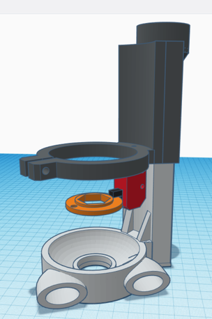
The optical sensor is built into the adjustable dust/vacuum foot that lives at the cutting head.
|
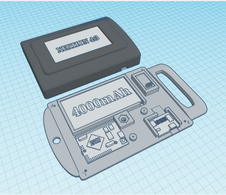
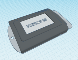
The case for the handset was designed in Tinkercad, and 3d printed in PLA.
I could probably shrink it down even more, but I do suffer from making my enclosures too damn small, so this time, I allowed room to work. It includes an integral nut, so the unit can be mounted on an adjustable arm at a later date if required. |
As usual, you find things you want to add as you go. I fitted a tilt sensor to the handset and a TIP122 transistor to the Nextion screen power supply.
I then programmed it so that the screen power is cut if the remote is not moved after 2 minutes. The screen powers back up when it senses movement.
I also added a small 5v relay on the serial lines to the Nextion screen. This connects the screen at boot, but allows me to program the controller 2560p without having to disconnect the Nextion screen every time I upload code (It won't allow programming with it attached).
|
It did become apparent quite quickly that the Nextion screen isn't all that responsive.
And the fonts that are supplied with the Nextion editor are nothing short of shockingly bad. I originally planned to have a 'Swipe' style movement system, so I could rapidly move the rig around the bed by swiping my finger in the direction I wanted to move. But, the screen just isn't responsive enough. So, I opted for a 'Tap to move' style affair. To tap the screen where you want to go, and the software checks you are within bounds. If it is OK, then press 'GO' and the rig will move to that point very fast. I also changed the left hand control buttons to operate the LED bed lights, the motor (or laser), the vacuum and a future allowance for a cooling fluid pump. I then added feedback to the receiver from the relays that control these pieces of equipment. |
The reason for the relay feedback is the receiver is live the second you power up the CNC machine. The handset however, might not be on at that time.
If you turn on the LED lights, or the router motor using another means (say the LCD screen controller), then when you power on the wireless remote, it needs to be told the state of the relays, so it can update the screen icons to the correct indicating state.
It's things like this you don't think of, until real life testing.
