|
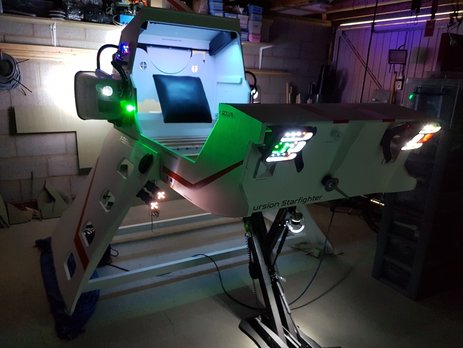
I started the project with the idea of having one Arduino mini pro running most of the lighting and sound effects.
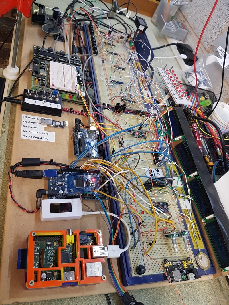
However, as usual... I got excited by my own cleverness and soon did what do every time. Filled the chip to the max and then had to upgrade. As you can see by my development board on the left, its got a little bit more involved. The first task was to work out these MP3 and Wav modules. I purchased a Wav trigger module from Sparkfun that apparently had the ability to play up to 14 stereo tracks at once. The key word there I found out was 'Up to'. Didn't take long to find a few flaws with the module (its still very good however). I was hoping to use its ability to alter pitch for the engine note, but it only adjusts by one octave, and it affects all the tracks playing at the same time. You cannot simply alter one track. Also, it was supplied with basically an old copy of the firmware that did not allow reporting back of the current playing track details. After messing around for an evening trying to get the firmware to update, I gave up and left it as it was. In the end, I found an old TBD380 MP3 module lying around my workshop. This lets you play up to 200 MP3 files by serial connection. |
So, after converting my voice files (made in Wavepad) from Wav to MP3, (I have converted files SO many times during this project), I loaded those onto the board.
There are currently 130 voice commands. That is bound to rise further.
The Wav trigger module is in charge off all sound effects, and the music. It simply knows the music tracks by number, rather than pull the actual track data off the MicroSD card. I may play around with that later to see if I can enable data retrieval, but its not essential now.
These sound modules are REALLY fussy about the sound file format. They must be 44.1khz, stereo, 16 bit.
Once you have loaded the files onto the SD card, you need to sort them with Drivesort. Its free file sorting software.
This sets them in the correct order on the card for retrieval, otherwise they don't play in the correct order.
I soon found out the the Wav trigger also relies on the quality of your SD card. I ended up ordering a decently fast MicroSD (100mbps), so that it could keep up with the data stream. The cheaper SD cards made the sound chippy and garbled if you played more than 3 files at once.
|
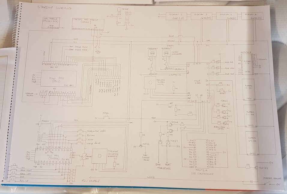
On the right you see my circuit diagram, updated as I go.
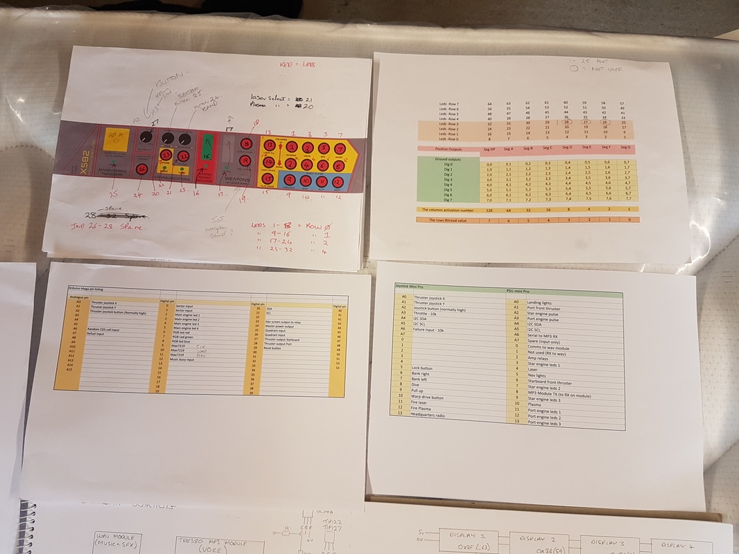
Below that are my spreadsheets listing various pin allocations, files numbers etc. Lets see if I can explain the basics of the circuit... We start with an Arduino Mega2560. This is an upgrade from the Mini Pro which did well until I unchecked a load of commented out coding in my program (stuff I didn't want running every time I tested it). That uncommented code bashed it over its program capacity. I had already completely rewritten a load of the code to save program space earlier on. So, the Mega is the heart of the system, based up in the cockpit area. This is the master I2C device. This then talks to a slave Mini Pro by I2C down in the PSU control box. This Mini Pro is in charge of switching on various engine leds, and passing information onto the Wav module and the MP3 module. The PSU box under the wing houses the amplifiers, so this was the best place to house the sound modules. The leds area all switched through appropriate transistors. It also switches in the speakers through a relay after the amplifiers have come on. This prevents speaker thump. Then there is a second Mini Pro based by the joystick. This also talks to the master Mega by I2C. This relays joystick inputs, the throttle position and various buttons (E.G. fire weapons). |
The master Arduino Mega does most of the work. This also talks to the 4x I2C 2x16 blue LCD screens.
These are set up as reporting screens for various functions on the spaceship.
These are set up as reporting screens for various functions on the spaceship.
Leds and illuminated button indicators
|
All the push buttons are illuminated on the control panel, and so these are controlled by a single MAX7219 LED controller.
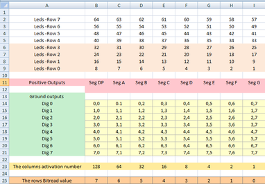
This gives me 64 outputs to enable me to illuminate any LED I wish over the serial link. You can see above in the top right a spreadsheet that lays out the rows and columns so that I can simply pull out a button number and gets its associated command to operate it. I will explain that a little more. |
|
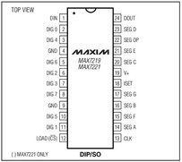
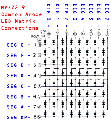
There are 8x Digit outputs (0v) and 8 Segment outputs (+).
When multiplexed, you can operate any combination of the leds you wish. So, my buttons (and any other leds I wish) are combined in groups of 8. So as an example, buttons 1 to 8 share the same Digit output - say Digit 0. Then, they each have an individual Segment run to each led. The diagram to the left shows the basic arrangement. So, to illuminate led 1, I would send a '1' to the Max7219 for digit 1. To illuminate led 2, I would send a '2'. To illuminate led 3, I would send a '4'. To light Led 4 would be an '8'. So, to illuminate all of the first four leds, I send 1+2+4+8=15. To then turn off led '1', I then simply deduct the number 1 again, so I send 14 instead. Make sense? So on the left here is the check chart for my leds.
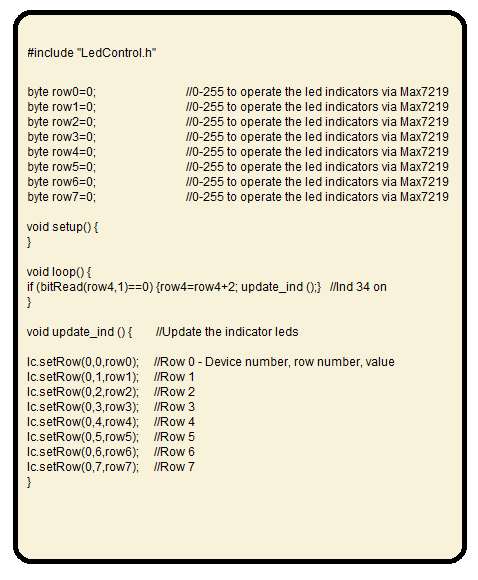
The buttons are numbered 1 to 64 at the top, and divided into rows. So, to operate the led in switch number 34 for instance, I would do the following. #include "LedControl.h" //Controller library for the MAX7219 Make a routine that updates all leds - 'void update_ind' in this case. Find the bit in the bottom row that corresponds to button 34. Number 1 in this case. Then note the row that the button is on. Row 4 in this case. Finally, note the columns activation number (2). |
|
The commands are as follows.
if (bitRead(row4,1)==0) {row4=row4+2; update_ind ();} //Ind 34 on This will check that bit number 1, in row 4 is off. If it is off, then increase the value of that row by 2. Then go to the update routine and it will update that rows leds. If you wanted to turn it off again, you simply check the other way and deduct 2. if (bitRead(row4,1)==1) {row4=row4-2; update_ind ();} //Ind 34 off The check at the beginning is purely to find out the state of the led before it updates. You could simply say: Row4 = 2; update_ind (); //Ind 34 on This would also turn on the led, but it would also clear all the other leds in the row. By reading the bit state, you can control the leds individually. Turning on the entire row would simply be: row4 = 255; update_ind (); //All leds on |
Button activation detection
|
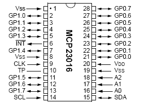
Actual button operation inputs are a bit more complex, especially as I have nearly 60 buttons. I used 4x MCP23016 multiplexed I2C I/O expander chips. They work on a similar principle to the MAX7219. I basically told the MCP23016 that is was 16x switches, and that watches for any of its 16 I/O pins to go high. When it does, it sends back a byte to the Master Arduino reporting the state of its 16 pins. It has two banks of 8 pins. IODIR0 and IODIR1. Wire.begin Transmission(0x20); // Setup MCP23016 controller for the button presses Wire.write(0x06); // Set to pin direction setting mode Wire.write(0xFF // Set controller IODIR0 to all input Wire.write(0xFF); // Set controller IODIR1 to all input Wire.end Transmission(); These chips are scanned each loop of the Arduino routine, and if any state of the input pins has changed, it then jumps out of the routine and checks the state of that chips 16 buttons as they are being reported back. It can then react according to what button has been pressed. A little code twiddling can mean you have either latching, toggling or momentary buttons. Its a slighty involved bit of code, but simple enough to get your head around. It works very fast and is great at catching multiple button presses at once. Plus, its easy to report back momentary or latched switches. |
As I mentioned, it reports back the state of that chips 16 pins as a byte. Button 1=1, button 2=2, button 3=4, button 4=8 etc.
So, all 16 buttons on will equal 255.
The Arduino code strips out the bits being reported back and then can work out which button was pressed.
We read the state of the pins using the following code (I have not included the definitions of the variables etc).
I did notice that I had to select the bank required, then end the transmission. Then request the pin state. Requesting the pin state byte within the bank selection routine did not work.
void Buttons_0to16 () {
Wire.beginTransmission(0x20); // Select first device
Wire.write(0x00); // Select bank GP0
Wire.endTransmission();
Wire.requestFrom(0x20,1); // Request the state of the GP0 inputs
B0to8_state = Wire.read();
if ((oldB0to8_state) != (B0to8_state)) { MCP23016_1_1_buttons(); }
oldB0to8_state=B0to8_state;
Wire.beginTransmission(0x20); // Select first device
Wire.write(0x01); // Select bank GP1
Wire.endTransmission();
Wire.requestFrom(0x20,1); // Request the state of the GP1 inputs
B9to16_state = Wire.read();
if ((oldB9to16_state) != (B9to16_state)) { MCP23016_1_2_buttons(); }
oldB9to16_state=B9to16_state;
}
We now have the state of the button inputs stored as bytes in the variables B0to8_state and B9to16_state.
It checks these against the last condition of the buttons (oldB0to8_state and oldB9to16_state) to see if anything has changed.
If it has, then go and see what button was pressed in the routines called MCP23016_1_buttons or MCP23016_1_2_buttons.
They are called the long names, as I have four of these chips, so I can then identify the correct routine for each chip easily.
I like to try and make my code addressing easy to understand, so when I return to it at a later date, I know what the heck is going on.
void MCP23016_1_1_buttons() { //Deduce which of the 8 buttons have been pressed
if (bitRead(B0to8_state,0)==1) { Button1 (); } //Setup as buttons
if (bitRead(B0to8_state,1)==1) { Button2 (); }
if (bitRead(B0to8_state,2)==1) { Button3 (); }
if (bitRead(B0to8_state,3)==1) { Button4 (); }
if (bitRead(B0to8_state,4)==1) { Button5 (); }
if (bitRead(B0to8_state,5)==1) { Button6 (); }
if (bitRead(B0to8_state,6)==1) { Button7 (); }
if (bitRead(B0to8_state,7)==1) { Button8 (); }
}
void MCP23016_1_2_buttons() { //Deduce which of the 8 buttons have been pressed
if (bitRead(B9to16_state,0)==1) { Button9 (); }
if (bitRead(B9to16_state,1)==1) { Button10 (); }
if (bitRead(B9to16_state,2)==1) { Button11 (); }
if (bitRead(B9to16_state,3)==1) { Button12 (); }
if (bitRead(B9to16_state,4)==1) { Button13 (); }
if (bitRead(B9to16_state,5)==1) { Button14 (); }
if (bitRead(B9to16_state,6)==1) { Button15 (); }
if (bitRead(B9to16_state,7)==1) { Button16 (); }
}
Here, we check the state of the bit within the returned byte to see which button was operated (or combination of buttons).
Then is simply jumps to the routine for that button.
If you wanted a toggle switch facility instead of a momentary button, then you could do this:
if (bitRead(B0to8_state,0)==1) { Button1_on (); }
if (bitRead(B0to8_state,0)==0) { Button1_off (); }
Here we are simply checking the state of the bit and sending it to an on or off line, depending on the returned but state.
The bit will be held high by the fact that you are holding that input high with a switch, not a momentary button
Latching momentary push buttons are simply achieved using a simple boolean toggle at the button action line.
Wire.beginTransmission(0x20); // Select first device
Wire.write(0x00); // Select bank GP0
Wire.endTransmission();
Wire.requestFrom(0x20,1); // Request the state of the GP0 inputs
B0to8_state = Wire.read();
if ((oldB0to8_state) != (B0to8_state)) { MCP23016_1_1_buttons(); }
oldB0to8_state=B0to8_state;
Wire.beginTransmission(0x20); // Select first device
Wire.write(0x01); // Select bank GP1
Wire.endTransmission();
Wire.requestFrom(0x20,1); // Request the state of the GP1 inputs
B9to16_state = Wire.read();
if ((oldB9to16_state) != (B9to16_state)) { MCP23016_1_2_buttons(); }
oldB9to16_state=B9to16_state;
}
We now have the state of the button inputs stored as bytes in the variables B0to8_state and B9to16_state.
It checks these against the last condition of the buttons (oldB0to8_state and oldB9to16_state) to see if anything has changed.
If it has, then go and see what button was pressed in the routines called MCP23016_1_buttons or MCP23016_1_2_buttons.
They are called the long names, as I have four of these chips, so I can then identify the correct routine for each chip easily.
I like to try and make my code addressing easy to understand, so when I return to it at a later date, I know what the heck is going on.
void MCP23016_1_1_buttons() { //Deduce which of the 8 buttons have been pressed
if (bitRead(B0to8_state,0)==1) { Button1 (); } //Setup as buttons
if (bitRead(B0to8_state,1)==1) { Button2 (); }
if (bitRead(B0to8_state,2)==1) { Button3 (); }
if (bitRead(B0to8_state,3)==1) { Button4 (); }
if (bitRead(B0to8_state,4)==1) { Button5 (); }
if (bitRead(B0to8_state,5)==1) { Button6 (); }
if (bitRead(B0to8_state,6)==1) { Button7 (); }
if (bitRead(B0to8_state,7)==1) { Button8 (); }
}
void MCP23016_1_2_buttons() { //Deduce which of the 8 buttons have been pressed
if (bitRead(B9to16_state,0)==1) { Button9 (); }
if (bitRead(B9to16_state,1)==1) { Button10 (); }
if (bitRead(B9to16_state,2)==1) { Button11 (); }
if (bitRead(B9to16_state,3)==1) { Button12 (); }
if (bitRead(B9to16_state,4)==1) { Button13 (); }
if (bitRead(B9to16_state,5)==1) { Button14 (); }
if (bitRead(B9to16_state,6)==1) { Button15 (); }
if (bitRead(B9to16_state,7)==1) { Button16 (); }
}
Here, we check the state of the bit within the returned byte to see which button was operated (or combination of buttons).
Then is simply jumps to the routine for that button.
If you wanted a toggle switch facility instead of a momentary button, then you could do this:
if (bitRead(B0to8_state,0)==1) { Button1_on (); }
if (bitRead(B0to8_state,0)==0) { Button1_off (); }
Here we are simply checking the state of the bit and sending it to an on or off line, depending on the returned but state.
The bit will be held high by the fact that you are holding that input high with a switch, not a momentary button
Latching momentary push buttons are simply achieved using a simple boolean toggle at the button action line.
The rest of the Arduino Mega's pins are used to sample local buttons. There is an analogue joystick module for the directional thrusters (there is also one on the joystick - reported by I2C from the Mini Pro).
The communications centre has a pair of rotary encoders that allow various tuning tasks to be completed.
Some pins simply switch transistors for the engine LEDS, and also 3x PWM outputs control the RGB leds in the cockpit.
This is the list of controls now available (and they all have voice announcement and SFX).
|
|
The joystick has the following inputs:
|
|
These are the initial designs for the Port and Starboard control panels.
I think these will now be redesigned, as I have added further functions, so I will probably add a new centre main control panel, and reduce the clutter on these side panels.
I think these will now be redesigned, as I have added further functions, so I will probably add a new centre main control panel, and reduce the clutter on these side panels.
