Time to make life easier
|
Every single time I build a prop, or a project, I end up with an array of individual boards splattered all over the place.
If the project involves sound, then we start introducing ground hums and noise due to the interconnecting (screened) cables. So, I decided to spend my 2021 Christmas designing a bespoke PCB to try and get all the 'usual suspects' onto one, sexy PCB. |
|
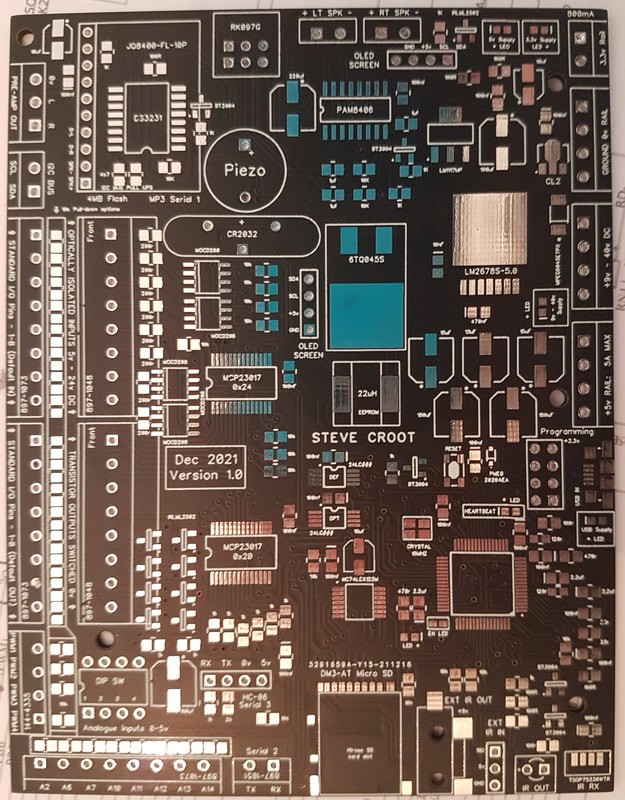
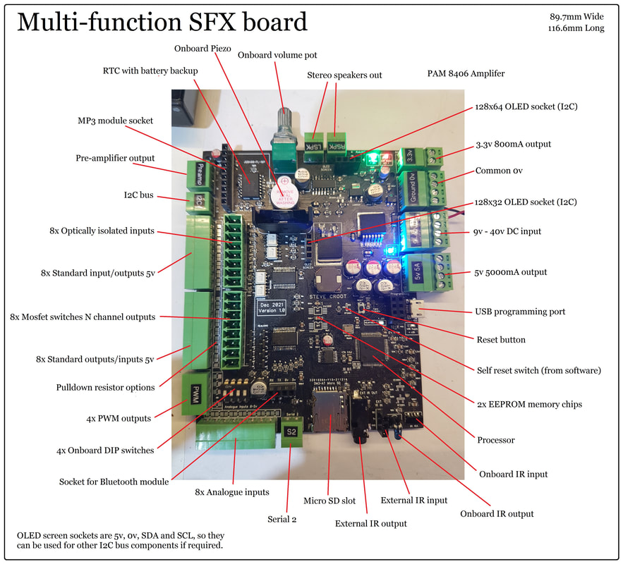
I had a list of what I wanted on the board:
- A 32 bit ARM Cortex-M4 72 MHz CPU
- 2x 24LC512 EEPROM memory chips (these can be any capacity)
- 1x PAM8406 Amplifier with onboard volume pot
- 1x JQ8400 Mp3 module with USB ability + pre-amp level breakout (Plug-in)
- 2x OLED display outputs (defaults to 128x32 and 128x64), but could run any display required (Plug-in)
- SD card for logging, data and text
- Onboard IR receiver and socket for external IR receiver
- Onboard IR transmitter and socket for external IR transmitter
- DS3231 Real time clock with battery backup
- HC-06 Bluetooth receiver (Plug-in)
- Onboard DIP switch for configuration
- 8x Standard TTL inputs
- 8x Standard TTL outputs
- 8x Optically isolated inputs
- 8x Mosfet switched outputs (N-Channel)
- 8x Analogue inputs 0-5v
- 4x PWM outputs
- Input ability 9v-40v DC
- 1x External serial bus
- Onboard 5v regulator
- Onboard 3.3v regulator
|
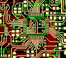
Now I have only been making my own PCB's a short while, so the learning curve was steep.
The first 'effort' is here on the left. I managed to keep it pretty compact at 89mm x 116mm. My plan is to make smaller versions with less features at a later date, but this one was to be the all singing version. The biggest issue was finding a 5v supply from a wide input voltage. The components are just impossible to find at the moment. I settled on an LM2675-5.0. Whether it turns out to be effective remains to be seen, but it is used in a lot of the buck voltage modules that come out of China. Speaking of China. Come on UK, I could not find any of the parts I needed to build this in the UK. RS and Farnell had less stock that I do, with some parts on a year back order. Digikey in the US supplied part of the components, but by far and away the majority came from AliExpress. OK, quality possibly suspect, but 10 times cheaper and here in 12 days. For instance, the 5v regulators from RS were £5.40 each +p&p. I got 3x for $6 from AliExpress delivered. |
I used a CP-3523MJCT-ND to drive a supply indicator LED. The SOT-89 device drops a supply of 5v to 90v, down to drive a supply LED at 22mA.
This is something else I did have a few struggles with. PCB footprints. Much as I tried, I could not get the RS PCB footprints to load into my DipTrace PCB software. Even using a 3rd party app, it failed miserably. I ended up drawing the pad layouts by hand in many cases.
This is something else I did have a few struggles with. PCB footprints. Much as I tried, I could not get the RS PCB footprints to load into my DipTrace PCB software. Even using a 3rd party app, it failed miserably. I ended up drawing the pad layouts by hand in many cases.
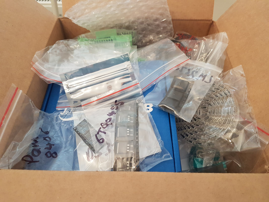
Most of China has arrived
|
So this morning, a lovely box of goodies arrived.
First impressions are that most of the components seem correct. Maybe the holes for the PCB connectors could do with being 0.2mm larger, but that is easily attended to. As for the design itself. Not much to say really. The JQ8400 Mp3 module is my 'go to' sound unit. Communications is over Serial. The inputs and outputs were expanded using a pair of MCP23017 multiplexers. These talk to the processor over I2C. |
|
The HC-06 Bluetooth module socket is on it's own serial bus. Future improvements of this board will include an actual Bluetooth IC, but for a first version, I went with a cheap, well known, plug-in board.
I have used the PAM8406, and PAM8403 amplifiers before, and they seemed pretty decent. Time will tell if that was a good choice.
If I need louder amplification, then there is a pre-amp header on the board.
I have written a basic Arduino IDE code to test the board with all of it's sub-boards plugged in. I will use that for evaluation.
All I need to do now, is get my eye in for some fiddly SMD soldering!
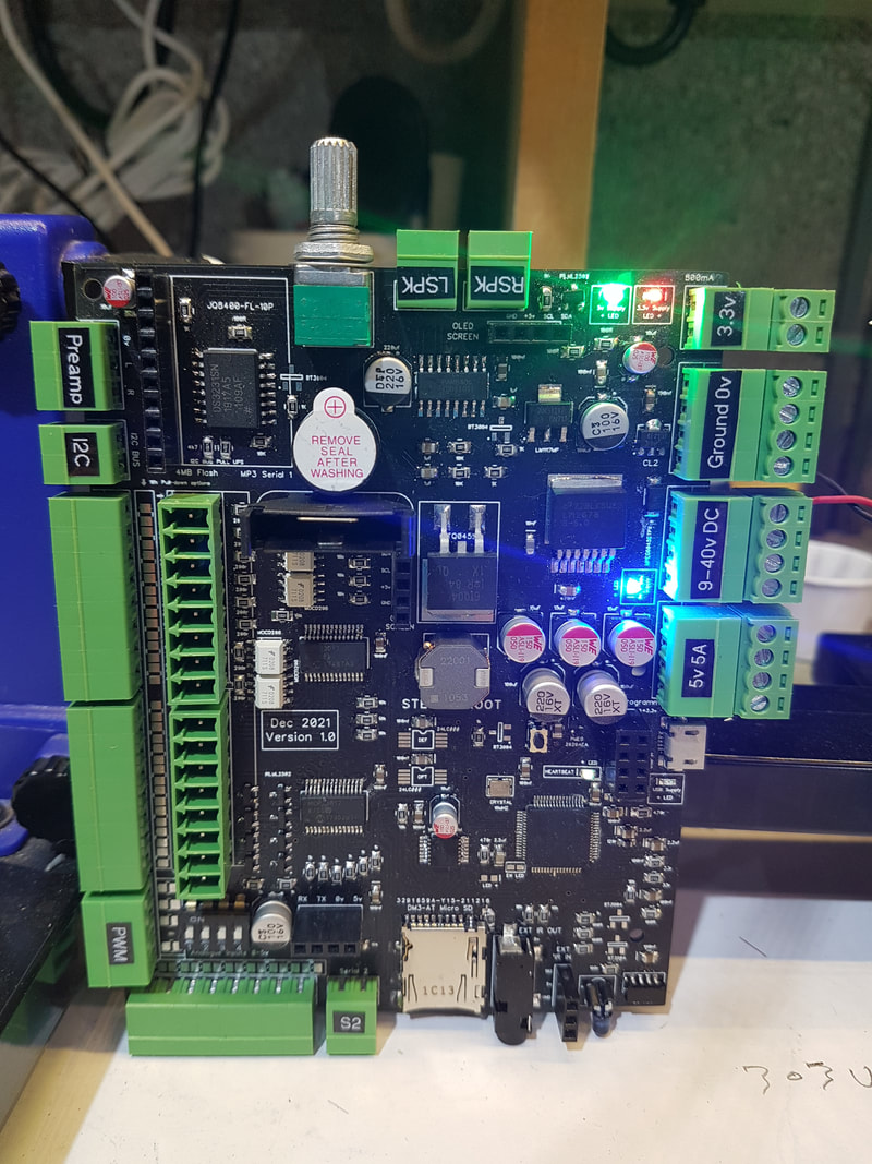
It's alive!
|
|
So far, no real component installation issues. Maybe a few of the holes for the edge connectors could be 0.2mm larger and I had one 10K resistor that was a little too close to the SD card slot. Apart from that, it is nearly fully populated.
The 128x32 OLED display needs moving right 1.1mm to line up with the 128x64 display (if you had them board mounted).
One thing I will do is widen the board slightly and make the 10k pull-down resistors easier to access. They are a little tight to solder between those board connectors.
I may also add LED's to the inputs and outputs.
Just waiting on some transistors, a couple of EEPROM chips and I can fire her up.
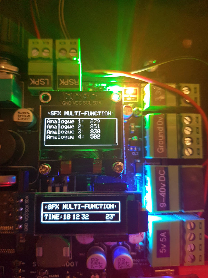
All systems (amazingly) go....
I will definitely move the pull-down resistors on the inputs, as they are a bit of a pain to add after the board is populated (but easy if you do it before fitting the screw-terminals!). Only part that fails the initial boot test is the extended EEPROM memory because it isn't there. I just cannot find any 24LC512 IC's with the correct SMD footprint in stock. The 2x OLED debug screens, the HC-06 Bluetooth module and the MP3 module all have small 3d printing support brackets, just to help them sit correctly. I think I may also add a 5v and 0v output next to the PWM outputs. Just handy if directly running a servo or something. |
So, I mounted the whole thing in a hastily 3d printed chassis and fitted that to a baseboard for ease of testing. Fired it up with a test routine I wrote, and all seems fine. RTC keeping time nicely, all the inputs and outputs appear to operate as expected and the PWM works fine too. My biggest concern was the amplifier, but that has come online perfectly. No interference or hum at all. Plenty loud enough as well. I may add an even larger amplifier to future designs, but this certainly drives the pair of 100mm speakers very well. The test routine simply checks each individual part of the board, and then loops around showing the input and output states of the pins. I can transmit a demo Infra-red code by operating one of the DIP switches, and it also displays incoming IR data or Bluetooth data on the screen as it is received. The entire PSU system seems to be coping very well, even with the load of the Bluetooth module. 
|
UPDATE 2023
So, it turns out that all the best plans and all that...
The MK20DX256VLH7 Cortex-M4 processor has become almost impossible to source, and it's not looking like it is coming back any time soon (if at ever).
So, I am now working on the next variation that uses an ESP32 as it's core processor.
You just never know.
Gee, at least I didn't put months of time into this..... oh wait