Tim Taylor would be proud.
Time to build another pimped man machine for the workshop
Whoo! Another machine to add to my collection of machines.
Started printing off the mad amount of parts required for this project.
It is based on the MPCNC (Mostly printed CNC) system, available for free on the V1 Engineering website.
Head over there. VERY nice people, very helpful and a great forum.
Started printing off the mad amount of parts required for this project.
It is based on the MPCNC (Mostly printed CNC) system, available for free on the V1 Engineering website.
Head over there. VERY nice people, very helpful and a great forum.
First of all, you need to decide what size you are going build this thing.
The temptation is to build it as big as you possibly can. But there are limits.
Build it too big, and you will introduce inaccuracy. You can add mid rail supports to help stop any travel rail flex, but does it really need to be that big?
'Z' height (the uppy downy bit in the middle) also need to be decided. I have seen quite a few builds with an excessively long Z rail.
This will probably (but I am no expert), make the centre assembly unstable. How far in reality will you actually be milling depth wise?
Not likely to be 8".
I settled for 800mm wide, 600mm deep and 200mm 'Z' travel. Mainly so you can lift it high enough to change milling bits.
This is all new to me I might add. Certainly no CNC expert!
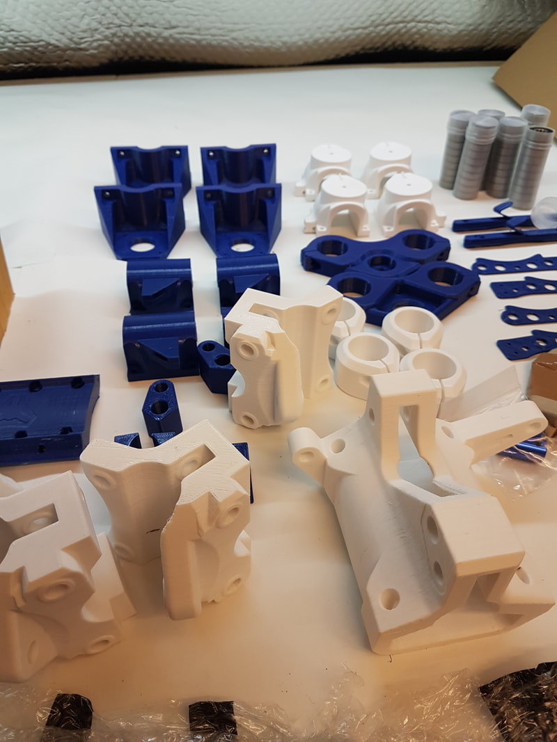
3d Print all the parts.
|
Oh
My God Print it in PETG they said. It will be fun they said. You download the 3d print files from the V1 Engineering website, after you have decided on what diameter tubing to use for the frame. I went for 25.4mm, as I had some welded seam piping already from another project. You can print it in whatever you like, and I imagine PLA would be perfectly acceptable. I believe all the parts take around 200 hrs to print in total. I have had PETG parts made for me before by 3rd parties, and they have been substantially stronger than the PLA prints, so I thought I would use that. Regret that idea. |
|
Hmm. Well at first my Flashforge printer really had issues with it. I ended up slowing the print speed to a ridiculous 15mm/s to get the parts to print.
They came out amazing. Very high quality, but I reckon it took 400+ hrs. By the end of this run of parts, I was ready to burn that bloody printer (meep, beep, blurr, wheeer, wheeer, zip, blurr weeeeeeeerrrrrrrrrrr).
They came out amazing. Very high quality, but I reckon it took 400+ hrs. By the end of this run of parts, I was ready to burn that bloody printer (meep, beep, blurr, wheeer, wheeer, zip, blurr weeeeeeeerrrrrrrrrrr).
Next, lets go shopping.
I already had some Nema17 stepper motors lying around, and a 10A 12v power supply.
I HATE Ebay these days, due to the fact that 50% of my purchases are scams, fake or come from China, even though I searched the UK.
So, I hit AliExpress which I have had a lot more success with (at least I know they are coming from China and have proper tracking).
I purchased a Rambo board and the associated LCD controller.
They arrived within two weeks, and all seems fine.
..The other items I obtained were 4 metres of 25mm plastic drag chain, the drive belts, sprockets, bearings and couplers.
There is a handy purchase list on the V1 website.
I also purchased a 600W router for the bargain price of £37.
After literally 2 hours searching through the workshop, I managed to scrape up enough nuts and bolts for the assembly.
There are full assembly instructions on the V1 website, but not that in-depth.
Ideally, you need to be a little bit handy to get this underway.
I did need to sit and draw this thing out (several times) to make sure I had my head around how it was all going to assemble. And I still got it wrong.
Twice.
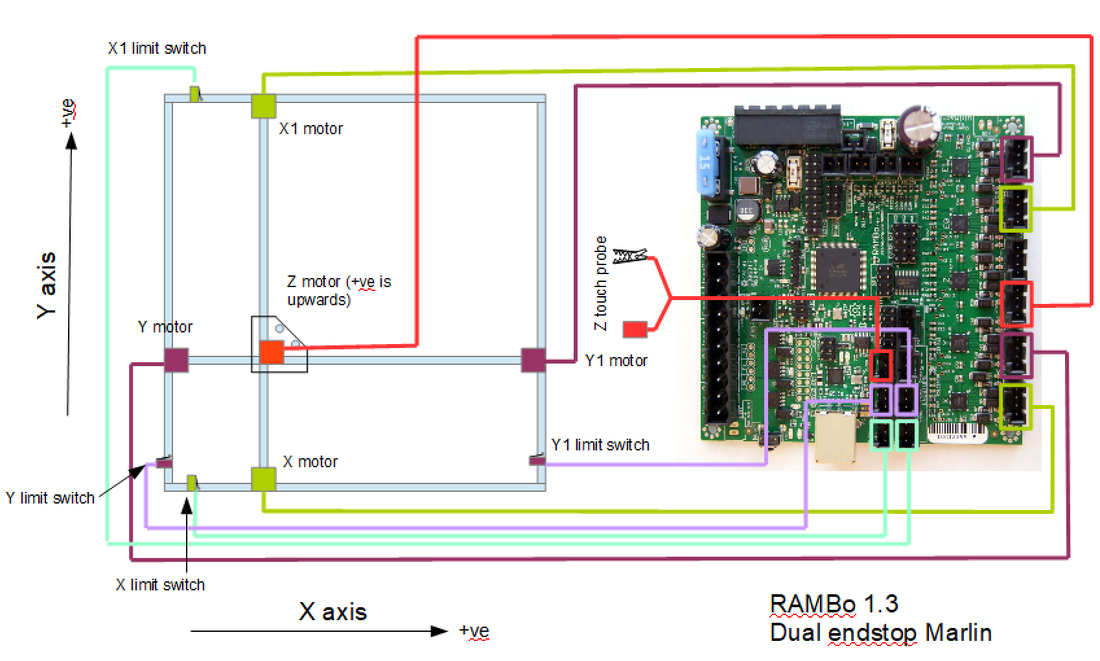
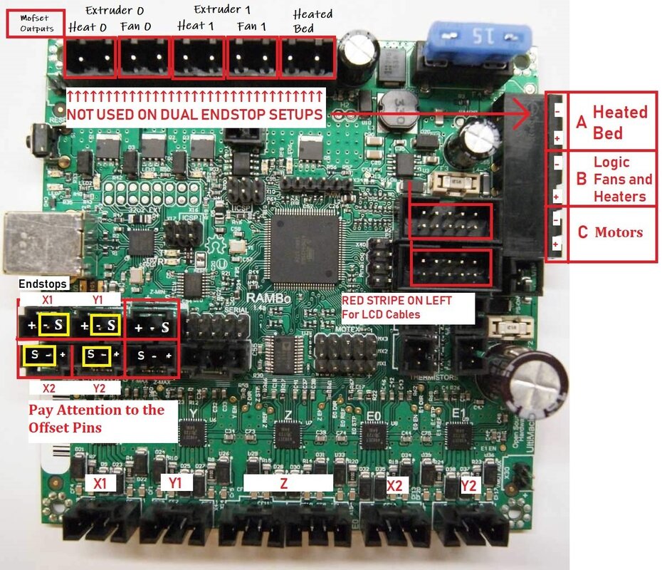
Wiring
Make sure you work out the wiring you require. Then work it out again.
I 'thought' I had my wiring worked out, and promptly threw in a whole load of cables.
Then I realised that ideally, the stepper motor cables should be screened. So, out they came again and I ran 8 core screened cables instead.
When I came to connect it all up, and after some head scratching (with how to get the steppers and limit switches connected), It became apparent that I was short of cores.
As the assembly page instructed, I wired the stepper motors in serial. So a pair of steppers only used 4 cores. The other 4 cores I used for the limit switches.
But, then (once it was bloody connected) it became obvious that if you are using limit switches, you ignore the instruction to wire the motors in series and you wire them individually.
So now I need more cores. ARGGHH. And now my 25x15 drag chains were packed full and installed.
Time to pimp this baby.

|

|
Now, as always, I can't make it simple.
I plan to add a laser at a later date, so I ran wiring in advance for that. Basically a twin supply cable for the laser and a twin cable for a cooling fan. I also ran an 8 core screened cable to all the rails (for the stepper motors) and also a spare cable to the 'Z' mount for auxiliary future equipment. |
I sat for a few evenings and designed the extra parts I required.
A connections 'tower' for the 'Z' assembly. This gives me somewhere to connect all my cables, and mount some multiway sockets for the Laser and Aux connections.
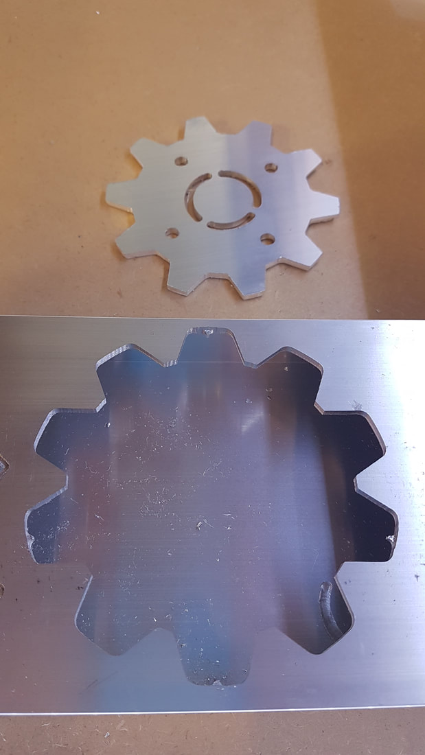
It also houses a 4mm socket that will have the 'Z' probe plugged into it on a curly lead. There is a second one of these leads on the baseboard.
These allow you to zero the height of the tool. You clip the lead to your milling bit, and then lower the 'Z' tower until it touches a metal plate attached to your other lead. This sets the height.
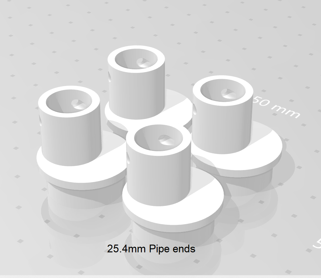
I also designed various clips for the drag chains to mount on, and pipe ends to give the cables a decent entry/exit from the steel pipes.
When I get time, I will assemble a downloads pack of all these parts.
I searched Thingyverse and found a nice LCD housing. I extended the width, so that I could fit in a couple of illuminated buttons to control the deck lighting and either the vacuum (to be added), or the milling head motor.
A connections 'tower' for the 'Z' assembly. This gives me somewhere to connect all my cables, and mount some multiway sockets for the Laser and Aux connections.
It also houses a 4mm socket that will have the 'Z' probe plugged into it on a curly lead. There is a second one of these leads on the baseboard.
These allow you to zero the height of the tool. You clip the lead to your milling bit, and then lower the 'Z' tower until it touches a metal plate attached to your other lead. This sets the height.
I also designed various clips for the drag chains to mount on, and pipe ends to give the cables a decent entry/exit from the steel pipes.
When I get time, I will assemble a downloads pack of all these parts.
I searched Thingyverse and found a nice LCD housing. I extended the width, so that I could fit in a couple of illuminated buttons to control the deck lighting and either the vacuum (to be added), or the milling head motor.
|
The base was 100mm x 25mm aluminium box section, with an aluminium angled rail riveted around the inside.
On top is a thick MDF baseboard, with further angled aluminium cross supports underneath. This thing needs to stay flat. All the electronics will be mounted underneath. A piece of lightweight ceiling grid angle made a great support for the drag chain that feeds the centre 'Z' tower. The brackets again came from Thingyverse. |
|
I mounted 5v white leds around the inside of the frame. My old man eyes need all the help they can get these days.
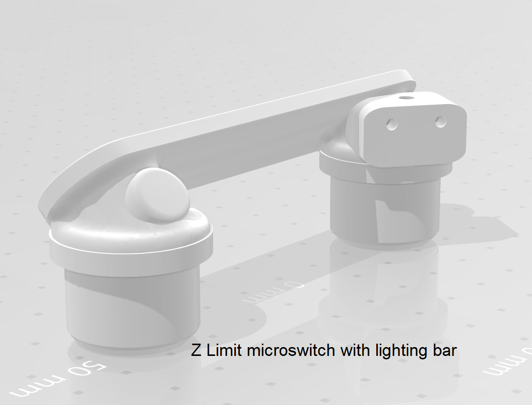
I also adapted a 'Z' rail base piece (on the right here) that allows me to have white leds facing the milling head, and also a microswitch to operate the 'Z' height max limit switch. I did add limit switches to all the rails. You can download a different 3d part to mount microswitches on if you wish to add them, but they are not actually required for a standard CNC setup (I believe). |
|
|
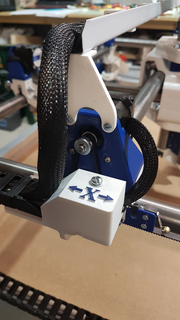
Connections to the X and Y stepper motors are made at the ends of the rails, and I believe most people are basically stuffing them down the ends of the pipe.
I wanted something a little easier to deal with, and with the ability to get at for changes or repair. So, I 3d printed a couple of housings (shown left) and made all the soldered connections in these. The limit microswitches also join here. They are wired normally closed as a fail-safe. Stop button. YOU NEED A STOP BUTTON. Several times now (mainly while playing around with Gcode commands, I have watched the Z stepper try it's best to thrust the milling bit through the bed. |
|
|