Learn my little processor
Over in my projects list, I have a Starship build.
This madly over-complicated affair has a navigation console that lowers across the bed using a 12v, 100mm linear actuator.
I needed some way of reversing this actuator if it encounters an obstacle.
There are already finger-trap sensors on the hinges that operate the reversing relays, but this circuit here was to protect the lowering of the console in general.
The console itself is controlled by a selection of relays. One of these relays is a dual coil latching type.
These coils are triggered by simple illuminated push buttons supplying 12v. One coil is for open and one coil is for closed.
Therefore, any safety detectors simply have to apply a 12v pulse to the 'open' coil.
|
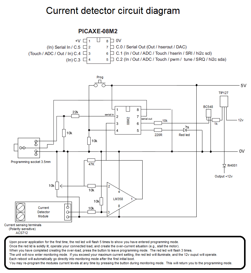
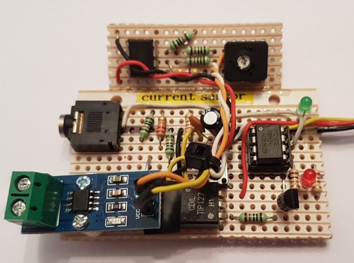
I thought I would use an 08m2 Picaxe chip, as it is a very basic circuit really. A long while ago, I purchased a current detector module from China for about £1.50. It is based on the ACS712 hall effect sensor. You basically apply 5v, and it issues an analogue signal depending on the current passing through the terminals. This particular module is a 0-30A detector. Far too high for my needs, but all I had to hand. My actuator appears to pull a maximum of about 2.88A when not obstructed. So, the circuit to the left is the final layout. Nothing special really. The output is a BC548 triggering a TIP127 to switch 12v to my 'open' relay. There is a simple PCB mount 'prog' button and an output led. After the initial test, it soon became apparent that the module wasn't providing enough signal for the Picaxe to detect on its ADC input pin. I could have re-written the code and used ReadADC10 (0-1024) instead of the lower accuracy ReadADC (0-255), but I tried a different approach. |
|
WARNING. Stripboard bodge alert!
After a poke around my workshop, I found an old LM358 amplifier. I made up a simple circuit to boost the incoming signal. The 10k pot allows adjustment so that the motor 'running' signal is nicely in the middle of the Picaxe's detection range. The code itself is not pretty. My bad! There will be coders out there picking holes in it I am sure. It basically fires up and checks EEPROM address 0 to see if the program has ever run before. It is hasn't, then it enters programming mode immediately. This flashes the red led 5 times. |
|
It then leaves the red led on while it 'learns' the outer ranges of the current load its is detecting. So now is the time to run the motor and obstruct it, therefore creating load (and raised current).
When you are happy it has learnt enough, press the PCB button and it exits learn mode.
It then will immediately enter monitoring mode from each subsequent power-up. if you wish to re-learn the current levels, then press the PCB button either during monitoring, or during power on.
It learns the current both ways (negative and positive swing). Exceeding the values stored always results in the same 12v output, but that allows for the load to be connected through the current detection module either way. It does make a difference which detection terminal has the supply voltage on it.
|
You could edit the circuit to have dual outputs.
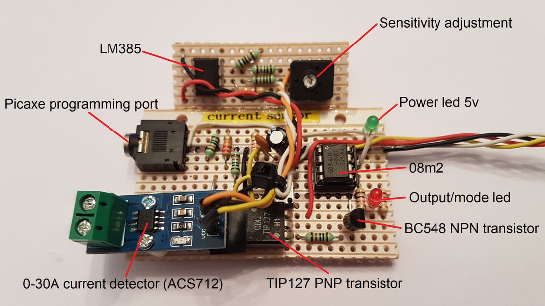
Pin 7 is only being used as the serial out pin, but it does have the ability to be used as an output. You could then simply have a pair of outputs that operate depending on which threshold has been exceeded. I added a stereo 3.5mm programming socket to the PCB. You don't really need to do this once it has been programmed, but I like the ability to simply plug in if I need to edit the code. |
The Picaxe code:
;Console over-amperage draw detector (auto reverse)
;Steve Croot 2018
;08m2
dirsc = %000111 '1=Output 0=input
symbol Transistor = c.1 'Output to trigger the relay (to reverse the motor)
symbol Redled = c.2 'Programming led
symbol Prog = Pinc.3 'Programming button input
symbol Current = c.4 'Input from the current sensor
symbol Motorload = b0 'ADC value from current sensor
symbol Upperlimit = b1 'Stored value from ADC sensor when under load
symbol Lowerlimit = b2 'Stored value from ADC sensor when under load
symbol Counter = b3 'General use variable for led flashing
symbol Firstboot = b4 'If this equals 0, then the code has never run
symbol Currenttotal = w3 'Total of 10x current samples
Upperlimit=170 'Set a default value in case this is the first run
Lowerlimit=120 'Set a default value in case this is the first run
Read 0,Firstboot 'If it retrieves 0, then its the first ever boot of the program
Read 1,Upperlimit 'Get pre-stored detection values
Read 2,Lowerlimit 'Get pre-stored detection values
pause 1000
high Redled
pause 1000
if Prog=0 and Firstboot>0 then 'If the prog button isn't being pressed, then go straight to main loop.
low Redled
goto main_loop
endif
DO WHILE prog = 1 'Wait for button release
LOOP
Upperlimit=0 'Set a default value to start from
Lowerlimit=255 'Set a default value to start from
low Redled
pause 1000
for Counter=1 to 5 'Flash led 5 times to show your in programming mode
high Redled
pause 150
low Redled
pause 150
next
pause 1000
high Redled 'Switch led on and wait for motor start
'--------------------------------------- 'Sample current when closing obstructed
Sample_close_obstructed_loop:
Gosub Sample_current 'Get load reading from detector
if Motorload>Upperlimit then 'Store highest reading
Upperlimit=Motorload
endif
if Motorload<Lowerlimit and Motorload>0 then 'Store lowest reading
Lowerlimit=Motorload
endif
if Prog=0 then 'Wait for button press
goto Sample_close_obstructed_loop
endif
low Redled
write 1,Upperlimit 'Set motor closing upper trigger load point
write 2,Lowerlimit 'Set motor closing lower trigger load point
DO WHILE prog = 1 'Wait for button release
LOOP
pause 2000
for Counter=1 to 3 'Flash led 3 times to show your exiting programming mode
high Redled
pause 150
low Redled
pause 150
next
write 0,1 'Set the first run flag
'___________________________________________________________________________________________________________________
Main_loop:
gosub Sample_current 'Get load reading from detector
if Motorload>Upperlimit then
gosub Reversemotor
endif
if Motorload<Lowerlimit then
gosub Reversemotor
endif
if Prog=1 then 'Wait for button press (to reset the module to default)
write 0,0 'Clear the first run flag
write 1,0 'Clear the limits
write 2,0
RESET
endif
goto main_loop
'___________________________________________________________________________________________________________________
Sample_current:
for Counter=1 to 5 'Flash led 3 times to show your exiting programming mode
pause 100
readadc Current, Motorload 'Get load reading from detector
Currenttotal=Currenttotal+Motorload
next
Motorload=Currenttotal/5
Currenttotal=0
return
'___________________________________________________________________________________________________________________
Reversemotor: 'Trigger the transistor to reverse the motor
high Transistor
high Redled
pause 500
low Transistor
low Redled
return