Additional electronics
When a switch is just too simple
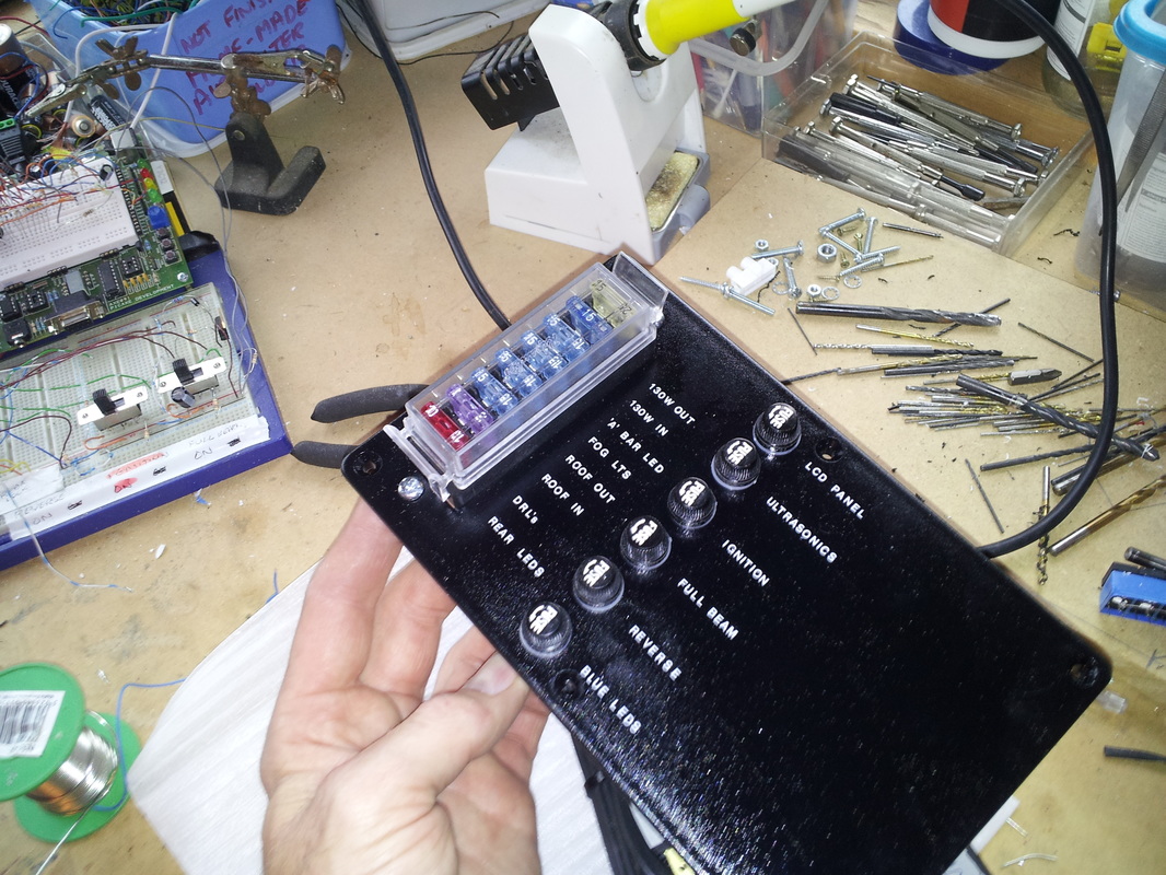
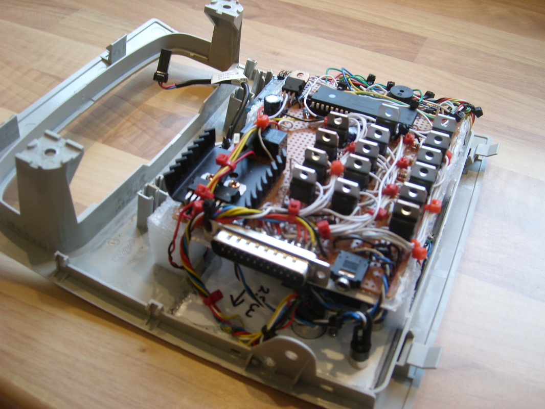
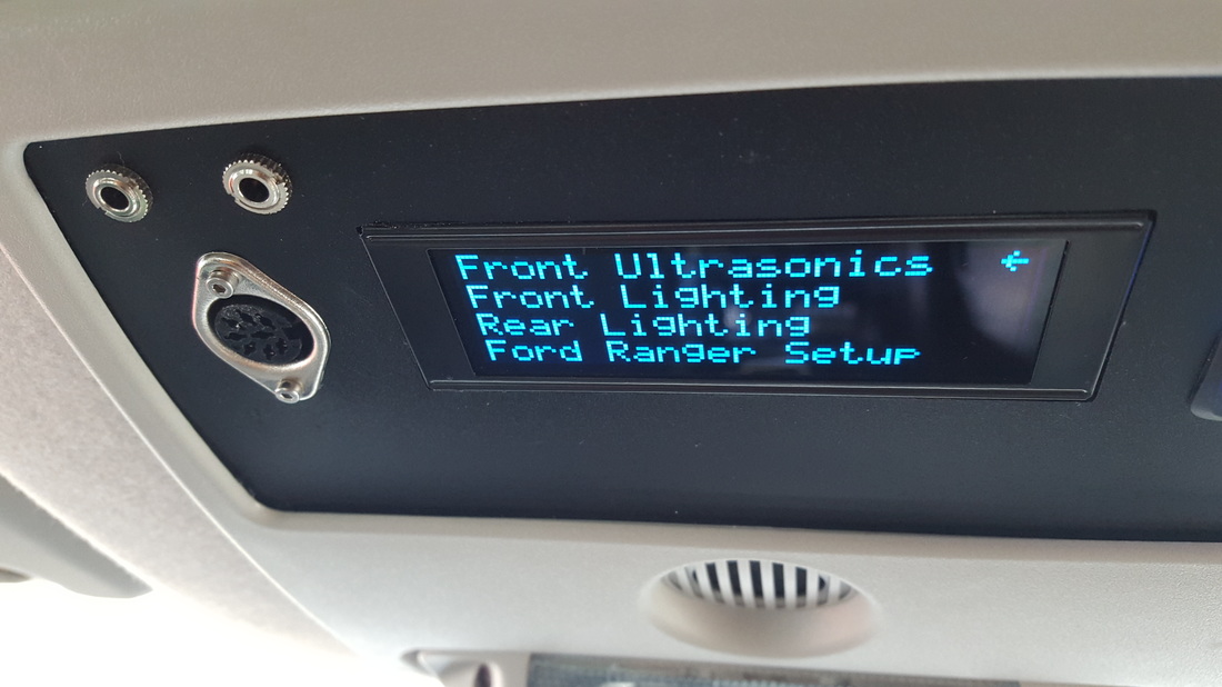
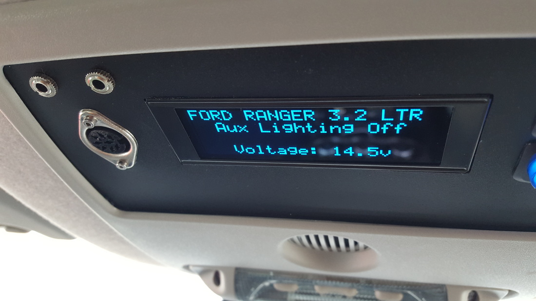
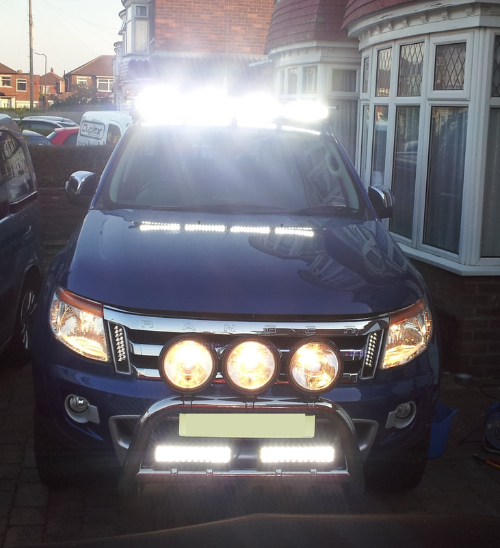
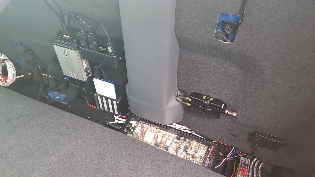
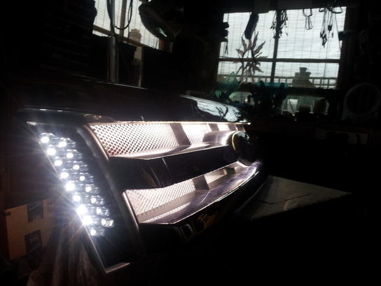
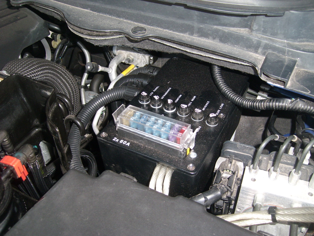
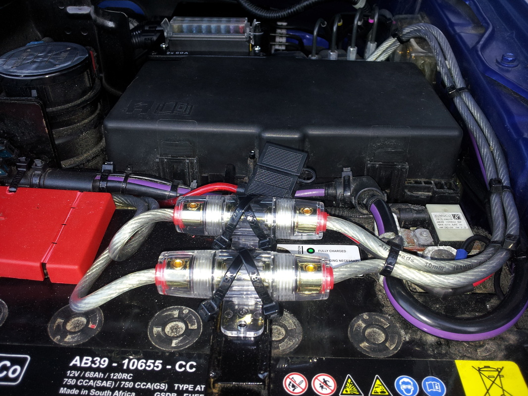
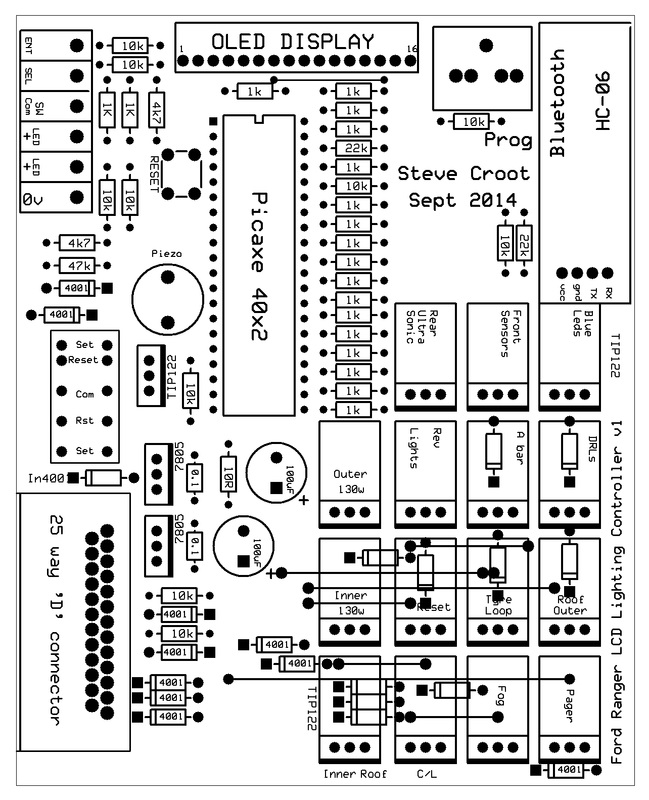
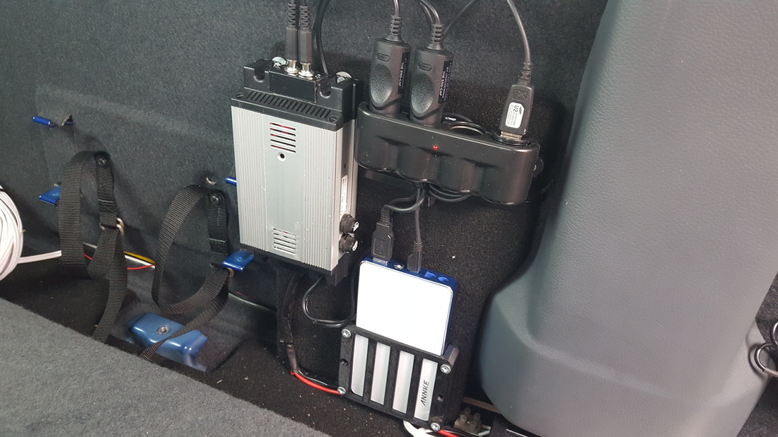
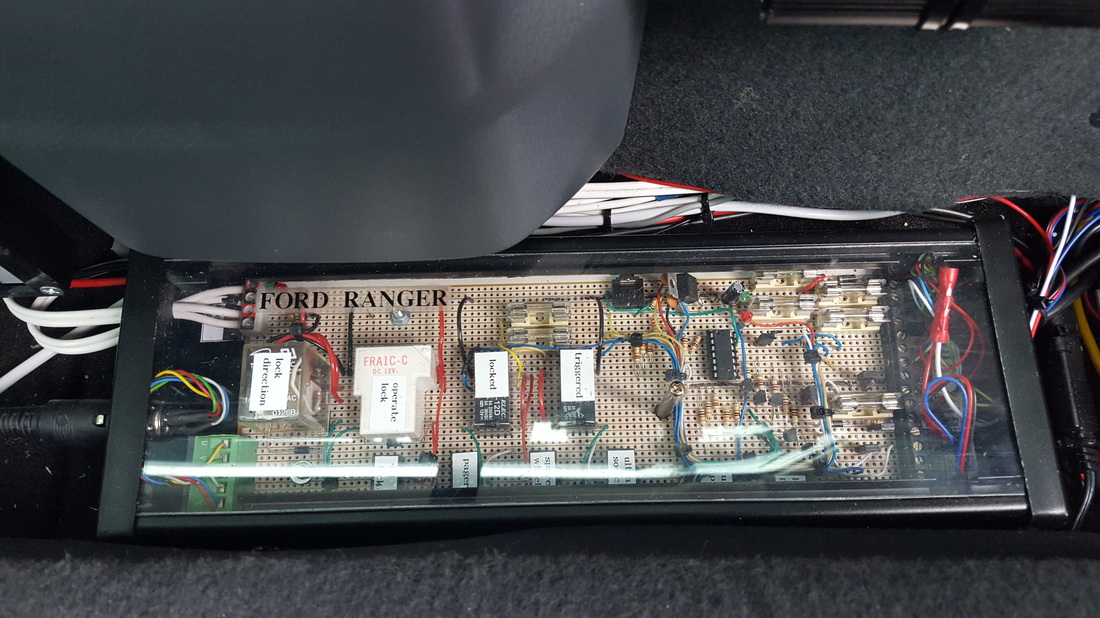
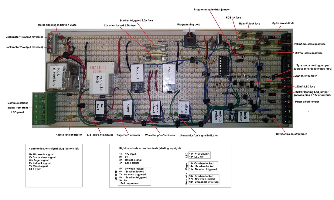
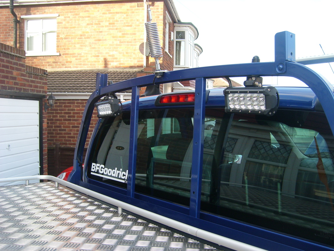
The first job was to install a separate fuse box. Ford Rangers (and most other new cars), don't like you adding things to the existing system. It can result in a very expensive burning smell from the main ECU. So, I made a new fuse box and fed this with a pair of 60A supplies. This box then sub-divides the circuits as required throughout the vehicle. Finding a spot to fix this extra fuse box turned out to be harder than you would think. Modern Rangers just don't have much space under the bonnet. This box also contains a large array of 30A relays. These are controlled by low current signals from my control system and switch all the high current equipment. The main lighting control unit is based on a 40x2 Picaxe chip. As the name suggests, it is a 40 pin chip with multiple inputs and outputs. I added an OLED display and fitted it into the space where the sunglasses holder was in the headlining. There is also a 14m2 chip from the same Picaxe family. This chips sole purpose is to montor bluetooth traffic and pass on any relevant commands to the main 40x2 chip. I custom wrote some Android software to control the truck lighting and other functions from my phone. There is also a wired remote, but controlling your headlights, spotlights and sundries by Bluetooth is a totally useless, but cool feature! Some signals are required from the trucks electrical system, so these were 'sampled' with a protection and anti-spike diode in-line. These simply told my computer system that the headlights were on, or had been flashed or perhaps the ignition was on. Protection and fusing is the key to vehicle electronics. I always err of the side of safety. Multiple fuses with diversity applied (smaller nearer the load) and you also suffer very large voltage spikes in vehicles. They will fry your lovely electronics pretty quick. There is a stepped menu that allows you to customise the entire system. They start under 4 main headings: *Front Ultrasonics *Front Lighting *Rear Lighting *Ford Ranger Setup The first menu is obvious. It toggles the front parking ultrasonic sensors on and off. The distance is displayed and they self cancel after 30 seconds. You press 'E' to cancel them earlier if required. The second heading of Front lighting leads to: *Lighting mode. What lights you are going to add to the full beam. *Full beam sequencer. Allows you to select what lights flash and in what sequence, when you flash the headlights. *DRL's. Whether the grille DRL's are on, off or ignition operated. *LED bar over-ride. Lets you switch on any LED bar individually. The third heading of Rear lighting leads to: *Rear LED bars. Whether they are off, on or operate upon reverse gear. The last heading is the setup menu. *Flash speed. The speed at which the headlight sequencer operates. *Blue interior LEDS. Interior lighting on, off or ignition. *Menu beep. Menu sound on or off. *Voltage monitor. Set a minimum voltage that must be available before that lights will operate. *LCD pin lock. Locks the lighting controller with a pin code. *Rear lid lock. Controls the rear Mountaintop lid locking. *Spare wheel loop alarm. Controls the loop alarm to protect the spare wheel while parked. *Load bay ultrasonics. Adds the load bay sensors to the truck alarm. *Page upon alarm. Whether the alarm system contacts me when the alarm is triggered. *Set defaults. Sets the system back to its default state You press and hold 'E' to add the additional lighting to the full beam. Press and hold again to remove them. Press and hold 'S' to switch the additional lighting to hazard mode. The lights then flash hazard style. The additional lighting: 2x 18W LED bars on the rear ladder rack. 4x 36W LED bars on the AEROBAR roof rack. 2x 36w led BARS on the front A' bar. 3x 130W spotlights on the front 'A' bar. There are white LEDS built into the sides of the grille, and white LED strips behind the grille mesh. Rear control panel: This a a sub circuit of the main front control system. It simply decodes the data from the main menu and carries out its instructions (for example, turns on the load bay ultrasonics). This unit is mounted behind the rear seat. I ran a spare supply to the rear seat area for a future sound system upgrade. Currently, the only thing running on this supply is the Sub woofer I added under the front seat. Also behind the rear seat is a 6 way sub fuse box. This controls local supplies. It also fuses the solar panel behind the rear seat that trickle charges the main battery. Above the rear control panel is the tracker unit with its GPS and GSM aerials. This texts me the trucks position, battery status etc, To the left of the control panel is an 8000mAh battery backup pack. This charges while driving and then powers the internal front and rear driving cameras while parked. Very handy for car park 'bumps'. The silver box on the left of the battery pack is simply a relay unit to control the charging. The battery pack is mounted in a bracket I 3d printed. Under the rear of the truck is the small module that has the spare wheel loop alarm. This is basically a loop of cable that goes through the spare wheel. Break it and the alarm sounds. It also contains a secondary sounder. Visit the current projects page to see the digital gauge system I am designing. |
|