LET'S GO MODULAR
|
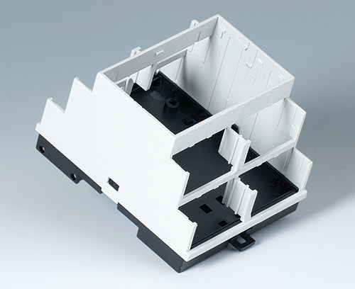
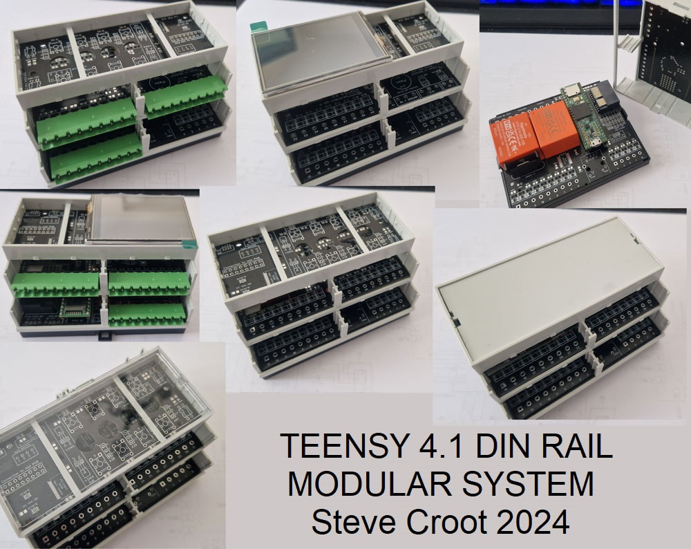
Teensy boards... These have become my default processors now. Lets make it a bit more universal for my needs. I searched around for a suitable range of Din enclosures that I could customise. OKW enclosures fitted that brief and they also sent me some free modules to design with. Just is case you didn't know, DIN stands for Deutsche Institut fur Normung. That roughly translates to “German Institute for Standards. The starting point is the CPU module. |
|
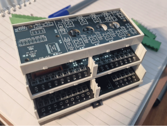
The main CPU module needs to provide for the rest of the items that may be attached to the right hand side of it when stacked on a DIN rail.
The Teensy 4.1 is mounted vertically with it's MicroSD card slot pointing out of the top. To the right of this I have fitted 2x Micro USB ports. One is an extension of the programming USB (Device) port and the other is the Host USB port. |
Underneath the Teensy 4.1 is a slide switch that lets you activate an onboard Piezo.
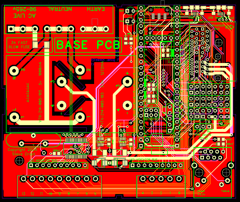
90-265v AC feeds (via thermal fuses) a couple of enclosed PSU modules. One give you 5v @ 1000mA and the other 3.3v @ 1272mA.
There is also a CR2032 battery for backup.
The PSU modules feed through a pair of i2c monitored current and voltage detectors. This allows the Teensy to display or record the usage of the power buses if it wishes.
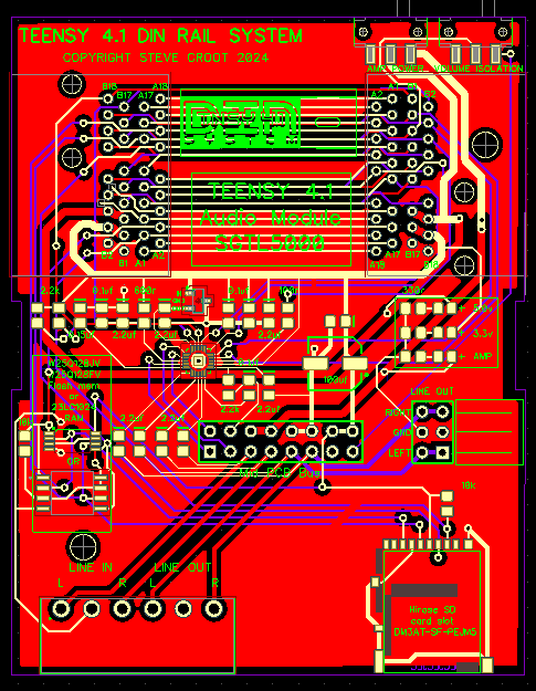
All the pins of the Teensy are broken out over two levels using 3.81mm centre plug-in screw terminals.
The mains input for all devices on the BUS system will be 5.08mm centre plugs so that you cannot connect the wrong plug into the module.
There is an onboard Ethernet socket and all outputs have an associated smd LED above them to indicate whether that pin is in used by an module plugged in further down the DIN rail bus system.
These LEDS are controlled the i2c addressed MCP23017 multiplexers.
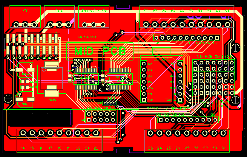
Most pins are then also brought out on a 1.6mm PCB right angle edge connector to extend the BUS along the din rail.
The Mid PCB has a footprint to install a Seeed XIAO ESP32C3 WiFi module if you wish.
A surface mounted 18 way socket links the mid PCB to the top PCB.
There are many options for the top PCB.
There is a multi-purpose board that allows for a 2.4" Touch TFT screen, buttons, magnetic hall sensors, rotary pots, small 0.91" Oleds etc.
You just populate as you require.
I also designed a test board that plugs into the bus socket with pads to help with testing and debugging.
The bus id system
All the slave modules on the BUS will need to be identified. This is achieved by allocating one of the Teensy 4.1's three i2c buses as the id bus.
Each module on the DIN rail will have the ability to select either the i2c id bus or the secondary i2c bus (this gives more address options).
The base code of the CPU module will then be able to identify when certain modules are plugged into the bus and both set up the communications correctly and illuminate any pins on the main CPU module that might now not be available to use (due to the pins being used by the slave module).
Slave modules
|
The next module along to the right will be the audio block.
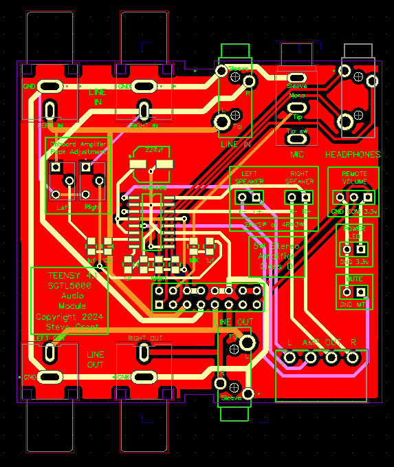
This is because the comms lines to the audio module need to be as short as possible. Teensy make an audio board that is based on the SGTL5000 audio module. It would make sense to design mine around the same audio processor so that the library that is already available is compatible. I could just plonk the Teensy audio board on my PCB, but where is the fun in that. Plus, I wanted to add a few extra features of my own. The base PCB has a couple of slide switches that allow a remote volume pot to be connected, and to control the power for the onboard amp. Below the 36 way Bus connector is a dedicated line output for an amplifier (when I get around to designing that!) |
|
At the bottom there is an SD card slot, dedicated to the audio board and the line in and line out terminal connectors.
I also added the ability to add extra memory for storing local audio files. The Mid level PCB has Phono and jack connectors for line in and out. A stereo headphone socket and a microphone input. A connector to fit a volume pot to the front panel (if enabled), and a mute connection. Then there is a PAM8406 5W stereo Amplifier. This can have a pair of speakers mounted in the top level of the enclosure (they are small), but the amplifier output is also brought out onto plug-in screw terminals. I also put a pair of pots to adjust the onboard amplifier levels. |
Further modules
|
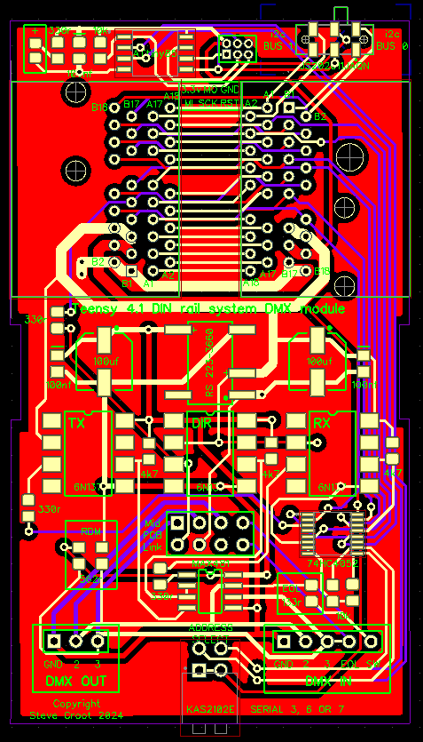
So far I have designed the following:
I am currently working on a dedicated 30w+30w Amplifer module for the audio block and a Mosfet switching module. And I have lots more in the pipeline.... |
