|
I have the wireless tablet. And it's a lovely thing.
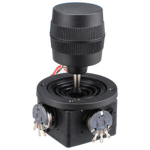
But, using a joystick to set your start position is even quicker. So, I bought a 3 axis Joystick from Ebay, and it arrived from China surprisingly quickly. Right, it'stime to start thinking like the Chinese chap who assembled it. It has 5 wires, and the two thin Yellow wires (about the thickness of a human hair), are clearly the top momentary button. This leaves the Red, White and Black for the hidden 'twist' 10k pot. Red must surely be + of the pot (far end of the track), black therefore would be the start of the track and white would be the wiper connection. NOPE. Red is 0v, Black is the centre wiper and white is +5v. I understand however that other joysticks have these same wires in different configurations, so check yours with a multimeter. |
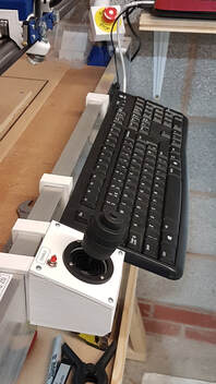
So now the joystick is here, I can 3d print a housing. I had the dimensions before it arrived, but I did not trust them. As it turns out, it was nothing like the dimensions on the Ebay page.
Various people wire up their joysticks differently, and I am no exception. Some use the top joystick button as enable, but I wanted that to be Reset Origin. I added a separate button to the casing for 'enable'. I wanted this joystick to deliberately be a two handed affair.
The button is held to +5v and taken low to enable the joystick.
|
You need to go into the Marlin software and edit the joystick configuration to suit your needs.
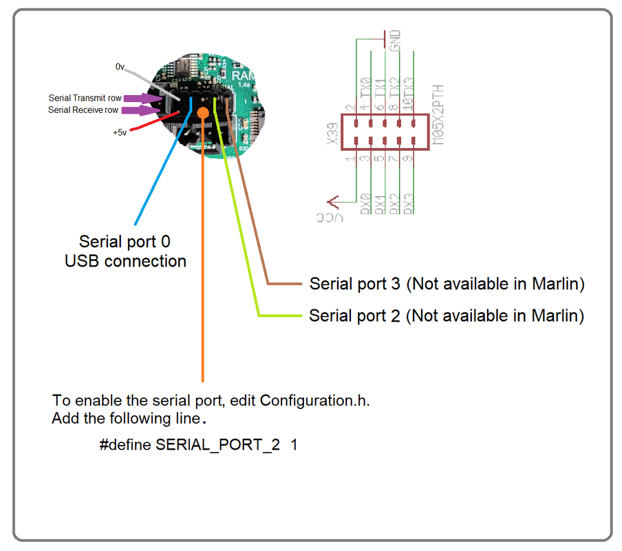
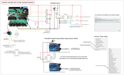
I used the connections shown in the diagram at the bottom of the page. You also need to enable the second serial port in the Marlin code, Configuration_adv.h. First of all, enable the second serial port: #define SERIAL_PORT_2 1 This tells the routine to use port 1 as the second serial input. There are pins on the Rambo 1.4 board for serial 2 and 3, but they are not enabled. The joystick also needs enabling by uncommenting #define JOYSTICK |
|
|
Once you have enabled the joystick and you are all wired up, you can test it.
Be aware that if you have enabled your joystick constantly with a switch (not recommended), then your CNC might fly off in any direction when you power up. Comment out the original joystick settings, take a copy of them and start playing with the values. I found the dead zones needed increasing substantially from 100 to 500. The lowest value is the bottom left of the joystick (well, in my case it is). I cannot really explain the best way to find this value. It can be done I believe using M119, but I simply tried values incrementing in 100 until I found the value that lead to a fast, smooth action. |
Once the value goes outside this sweet spot, it either judders, doesn't move, goes slowly or moves and then suddenly halts at the extremes of the joystick.
/**
* Analog Joystick(s)
*/
#define JOYSTICK
#if ENABLED(JOYSTICK)
//#define JOY_X_PIN 5 // These were the default pins that I am not using
//#define JOY_Y_PIN 10
//#define JOY_Z_PIN 12
//#define JOY_EN_PIN 44
#define JOY_X_PIN 3 // 3- Analog Ext 4 // These are the new pins I am using
#define JOY_Y_PIN 4 // 4- Analog Ext 6
#define JOY_Z_PIN 5 // 5- Analog Ext 8
#define JOY_EN_PIN 4 // PWM ext pin 6
// Use M119 to find reasonable values after connecting your hardware:
//#define JOY_X_LIMITS { 5600, 8190-100, 8190+100, 10800 } // min, deadzone start, deadzone end, max Default values
//#define JOY_Y_LIMITS { 5600, 8250-100, 8250+100, 11000 }
//#define JOY_Z_LIMITS { 4800, 8080-100, 8080+100, 11550 }
#define JOY_X_LIMITS { 0, 8030-500, 8030+500, 16800 } // min, deadzone start, deadzone end, max My values
#define JOY_Y_LIMITS { 100, 8500-500, 8500+500, 16500 }
#define JOY_Z_LIMITS { 200, 8080-500, 8080+500, 16500 }
#endif
G-Code injector
|
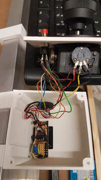
I wanted the ability to set my start point, so using the above IC, I made a simple routine to fire a serial command upon pressing a button.
The code is below, and I loaded it onto the ATtiny85 in my case, using a pair of Arduino Uno's. Purely because I had them. You can of course, use the proper programmer modules. One thing to note with the ATtiny85, is that the internal clock isn't all that accurate. I tried an external crystal, but it didn't really help. Slow baud rates worked fine, but my MPCNC runs at 250000 baud. It could not generate serial commands correctly with any internal or external clock. The fix was to add a multi-turn 10k pot and assign its value to OSCCAL. This lets you tune the clock. |
|
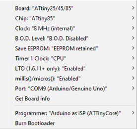
Remember to set the fuses on the ATtiny85 first. Internal 8Mhz clock etc. The exact setup I used is to the right here.
You will also need to add the ATtiny85 to your boards manager. I used the ATTinyCore v1.3.3. A quick Google should help you find the required board core. There are three buttons in my routine, but in my case, I only used the 'reset origin function'. Of course, you can change the Serial command to any G-code command you wish. Uncomment the MarlinSerial.print("OSCCAL = ");MarlinSerial.println(OSCCAL, HEX);delay(200); line while setting up the clock trim pot. Make sure the pot is a multi-turn type. Once you are seeing clear serial commands on the serial monitor, you have dialled it in. |
ATtiny85 code:
// ATTiny85 Based Serial G-Code injector
// Steve Croot
// March 2020
#include <SendOnlySoftwareSerial.h>
#define BUTTON_1 0 // Button 1 input (HOME XYZ)
#define BUTTON_2 1 // Button 2 input (HOME XY)
#define BUTTON_3 2 // Button 3 input (RESET ORIGIN)
#define OscTrim 3 // Crystal trim pot
SendOnlySoftwareSerial MarlinSerial (4); // Serial TX pin
unsigned long CurrentMillis; // Timer elements for delayed button press
unsigned long ButtonMillis;
int ButtonDelay=2000; // Button delay in milliseconds. Adjust to suit or 0 for off.
void setup() { //--------------------------------------------------------------------------------------
MarlinSerial.begin(250000);
pinMode(BUTTON_1, INPUT);
pinMode(BUTTON_2, INPUT);
pinMode(BUTTON_3, INPUT);
}
void loop() { //----------------------------------------------------------------------------------------
CurrentMillis=millis();
int val = analogRead(OscTrim); // Obtain the adjustment value
OSCCAL = val/4; // Adjust the oscillator
//MarlinSerial.print("OSCCAL = ");MarlinSerial.println(OSCCAL, HEX);delay(200); // Uncomment this line to help tune the crystal (DO NOT LEAVE ACTIVE ONCE TUNED!)
if (digitalRead (BUTTON_1) == HIGH){ // Button 1 command (Home all)
do{
if (millis()-CurrentMillis>ButtonDelay){
MarlinSerial.println("G28 X Y Z");
do{delay(2);}while(digitalRead (BUTTON_1) == HIGH);
}
} while(digitalRead (BUTTON_1) == HIGH);
}
if (digitalRead (BUTTON_2) == HIGH){ // Button 2 command (Home X Y)
do{
if (millis()-CurrentMillis>ButtonDelay){
MarlinSerial.println("G28 X Y");
do{delay(2);}while(digitalRead (BUTTON_2) == HIGH);
}
} while(digitalRead (BUTTON_2) == HIGH);
}
if (digitalRead (BUTTON_3) == HIGH){ // Button 3 command (Reset origin)
do{
if (millis()-CurrentMillis>ButtonDelay){
MarlinSerial.println("G92 X0 Y0 Z0");
do{delay(2);}while(digitalRead (BUTTON_3) == HIGH);
}
} while(digitalRead (BUTTON_3) == HIGH);
}
} //---------------------------------------------------------------------------------------------------------
As usual with anything to do with the Arduino IDE, I had a bit of a faff trying to find an actually working library, or one that was up to date.
Adapt it to your needs!
Adapt it to your needs!
