Time to build a box.
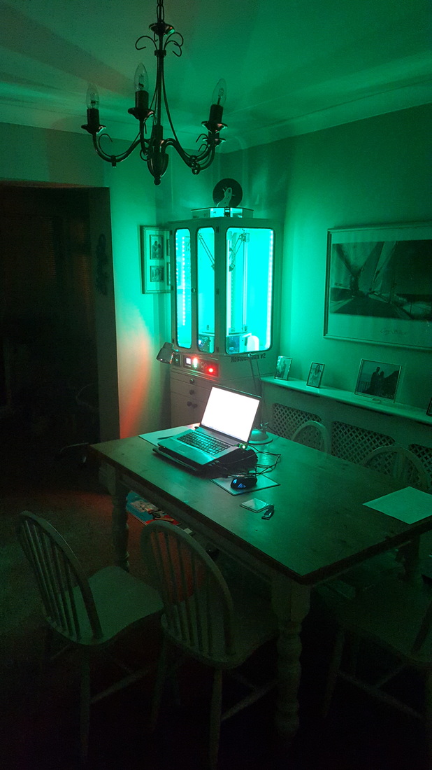
My 3D Rostock printer has been sitting on the dining room table now for many months.
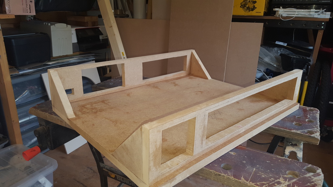
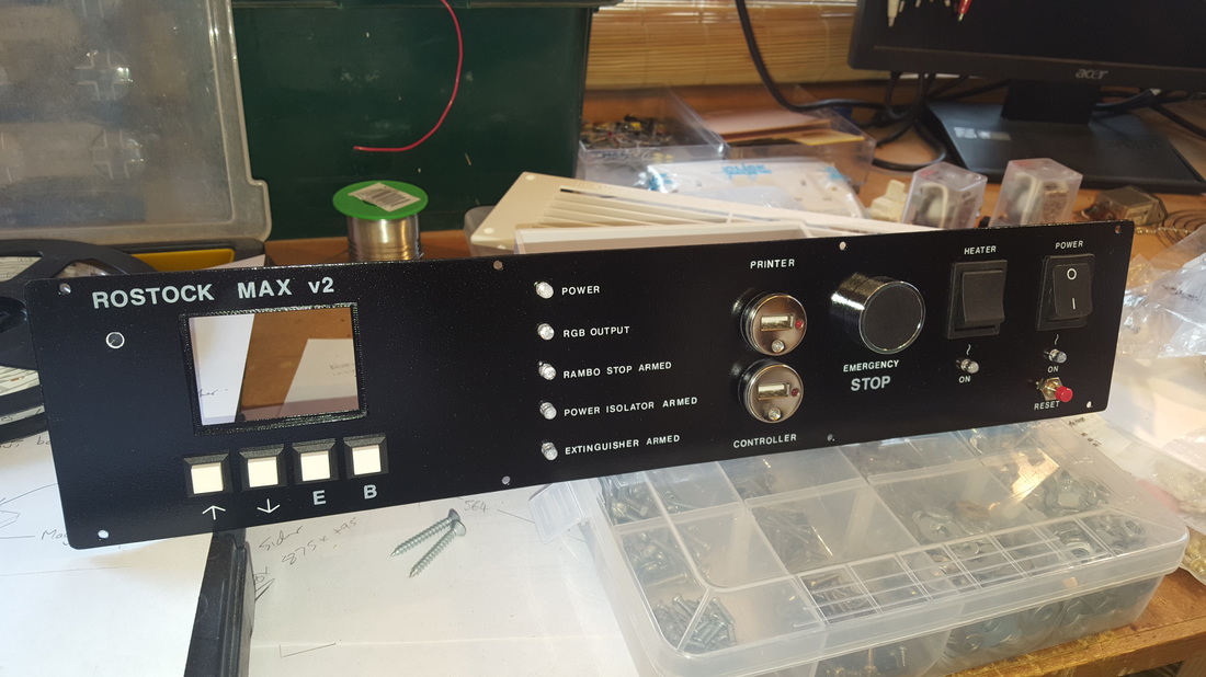
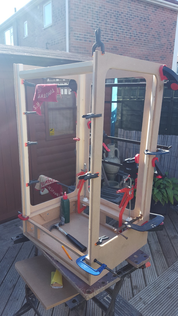
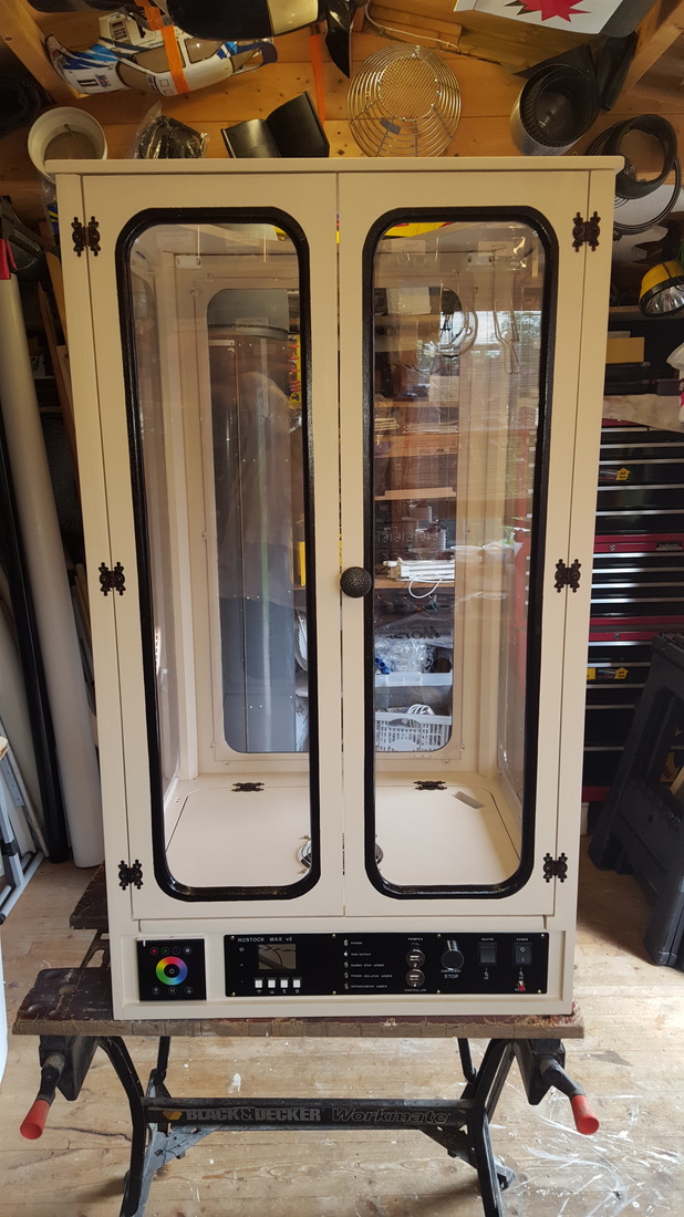
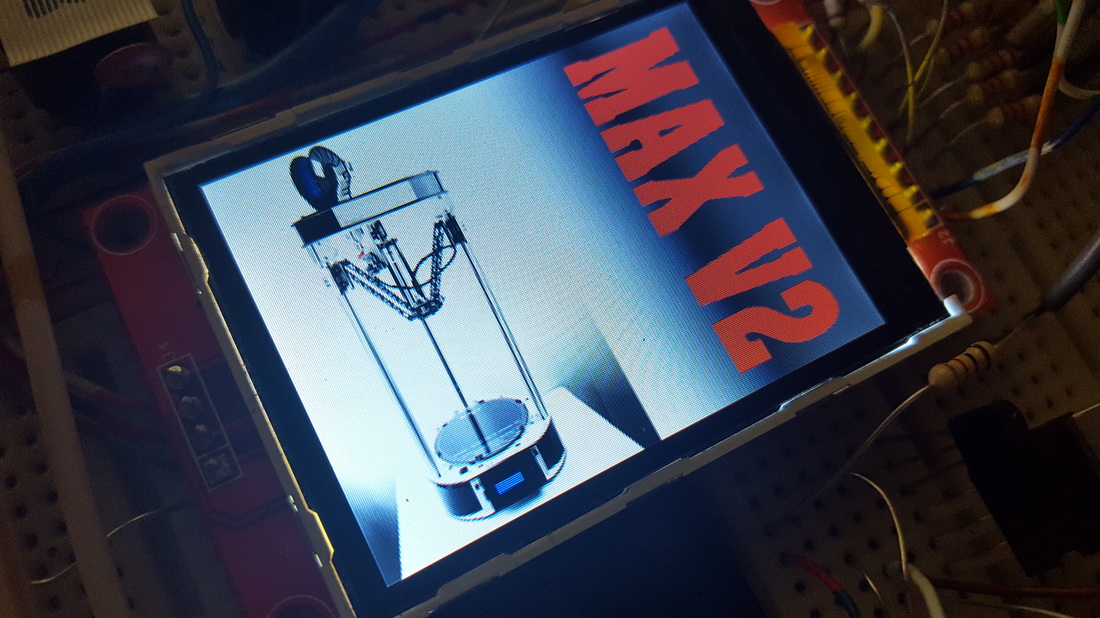
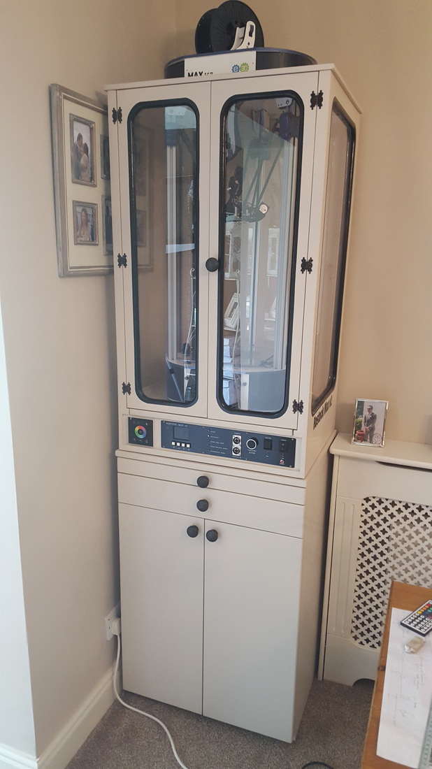
Time to build a heated cabinet for the thing. Dug out some MDF and got sketching. There are several 'features' that I wanted the cabinet to have. Safety is top of the list, as the printer gets left alone for hours on end. I don't want this cabinet to be known by the local fire brigade as 'point of origin'. The cabinet was basically MDF (yes I wore my mask mummy) with routed viewing windows on all sides. I ordered some 4mm Polycarbonate sheet online for the windows. The base unit consists of a decent sized dual door cupboard, with a draw above that for the laptop and a thinner one for tools at the top. The base unit can stand as a single piece of furniture if you wanted to take the printer and its enclosure elsewhere. I painted it with a tin of some neutral colour I found in the garage. Masked off the window edges and gave them a black detail with spray paint. Bought a couple of custom 'Rostock Max v2' decals for the sides (good old Ebay). The top lifts off with a couple of magnetic catches, This allows easy installation of the printer. The control panel was a piece of carefully drilled and filed aluminum. I then spent forever rubbing on some very old Letraset letters before clear-coating it. The heart of the electronics is an Arduino 2560p processor board. This is linked to a small 2.2" TFT colour screen. There is a 12cm fan drawing clean cool air into the case through the rear of the cabinet. It is forced up an through the grille on the base of the cabinet. On the side of the printer, there is a 9cm fan drawing the air back out and it will be directed down and out the back, |
|
|
|
The printer had a pile of extra bits added when I originally built it. These are accessed by a 25 way 'D' plug on the side.
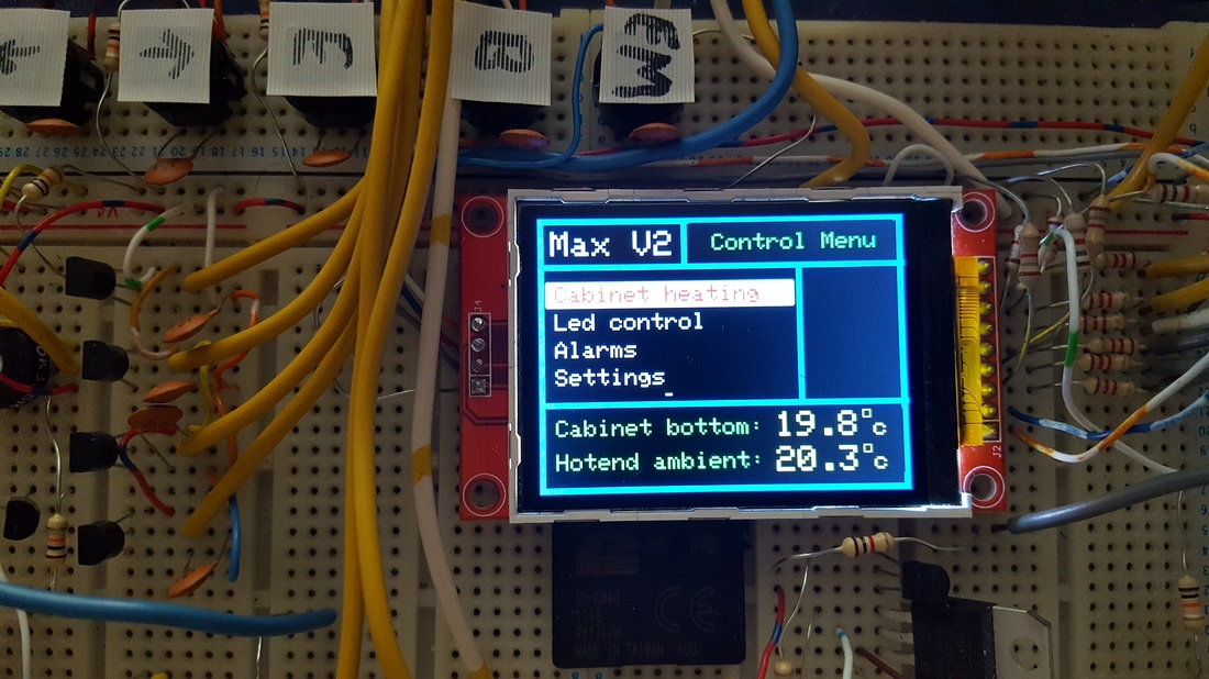
These extras include.. Remote access to the Led RGB ring on the hotend. Remote access to the RGB Leds that are inside the printer chassis. Output from the RGB led remote control module. Spare thermistor mounted on the Hotend. Relay coils that allow the switching of the RGB leds to an external control source. I wrote the Arduino software to control 4 separate Sections. 1) Heating 2) Illumination 3) Alarms 4) Settings |
Heating
Select heating, and you can set the temperature you want to reach inside the cabinet. 0-99 degrees.
You can also select sensitivity. This is the amount in degrees the temp can drop, before the heater switches back on again.
This is to prevent cycling of the heater elements.
Sensor selection. There are 4 thermistors mounted top, middle and bottom of the enclosure, and one on the end on the print head.
You can pick anyone of them, or an average of them all.
Enable auto-off. This is a countdown timer 0-99 hours. You can select a time in minutes and hours that will count down while the front panel heater switch is on. At zero, the heater switches off
Illumination
|
This menu accesses the input selection for the chassis RGB leds, the cabinet RGB leds and the hotend RGB led ring.
The source options are the local touch controller on the front panel, the remote control or a range of pre-set patterns and effects I wrote in the Arduino software. These pre-sets include options like fading from blue to red as the temperature increases, or fading red to green. Strobe effects (why would you want that?), chasing and other various colour changing patterns. |
|
Finally the backlight for the TFT screen can be set on, off or automatic. You can select the level of light that operates the backlight.
Alarms
Here you can set various warning systems and tones.
|
Beep at temperature. A simple beep when you reach the required level.
Alarm at temperature. A warning alarm if a certain settable level is reached (that you were not aiming for). You can also switch on an external sounder to really make sure you hear the problem. Alarm type simply gives you options to the sound you hear. Emergency stop. This menu will allow you to determine the outcome of pressing the STOP button on the front panel, and the alarm at temperature listed above. You can have either trigger stop the printer (operate the Rambo stop button), kill the power to the cabinet, or operate the fire extinguisher. Or, any combination of the above. The fire extinguisher is a future modification that I have written into the menu system now. When you kill the power, you have to manually reset the system by using the push button on the front panel. It kills all power to everything. |
Settings
The settings menu just allows you to customise the system a little.
You can set reporting speed. The speed at which the temperature, voltage and other information is displayed on the front panel.
Confirmation beep. Whether the buttons 'beep' or not.
Screensaver. You can select a temperature graph, pictures (loaded from the local SD card), a large random temperature display or combinations of these options.
Filament data. This feature allows me to load one of 99 files from the SD card (that also holds the screensaver images).
These files are the names and details off all my filaments, I simply have to update the SD card with a simple TXT file if I buy a filament that I have not already added to the library.
This menu allows me to recall the spool I am using and its weight when it was removed. There will be a load cell built into the spool holder on the top of the cabinet.
I can also re-calibrate the load cell or set a new weight (new reel of filament).
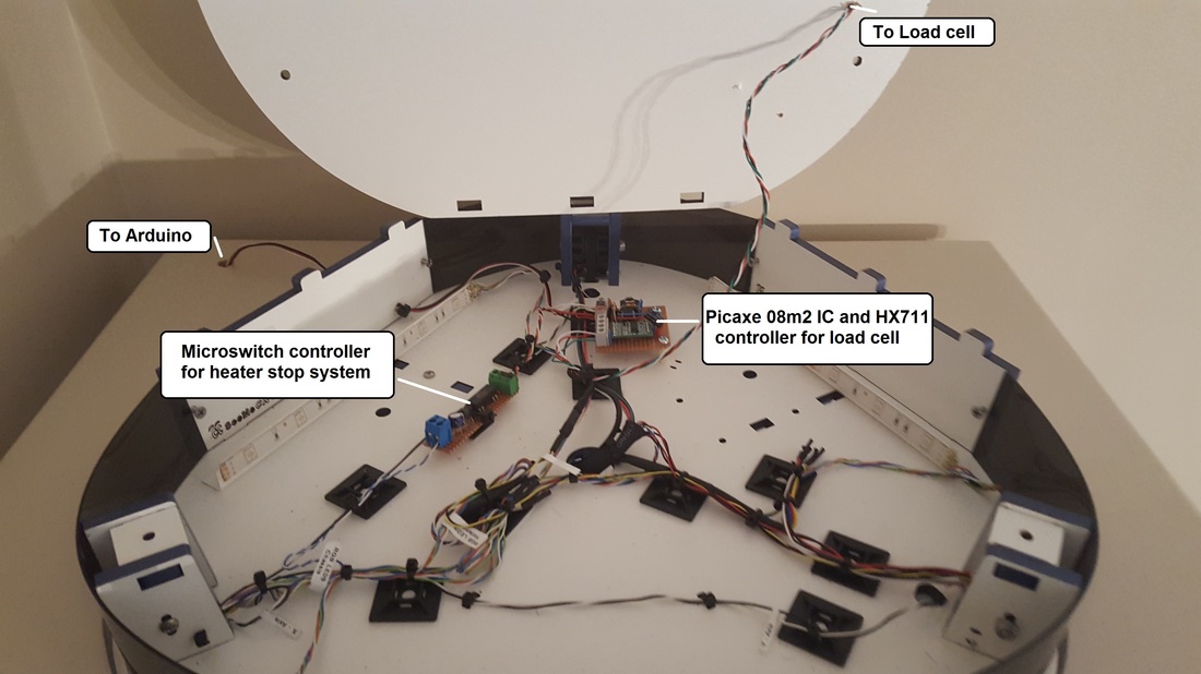
Internal circuit boardsAll the internal logic and control PCB's are now complete and installed.
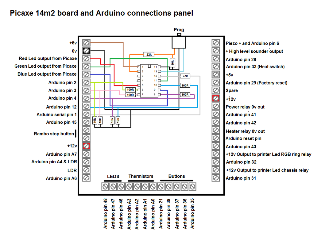
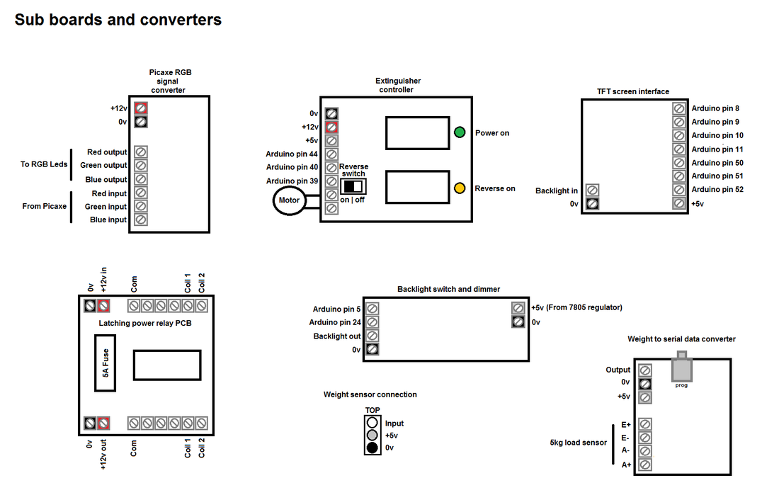
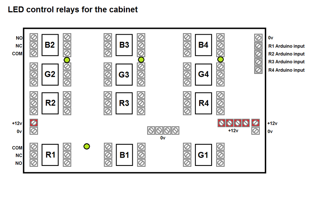
All I need to do is interconnect them! And that is no small task. A lot of the circuitry is logic to control the red, green and blue outputs for the illumination. There are a lot of various options for sources and destinations when it comes to the lighting signals. I achieved this with DPDT 12v relays. Very cheap (thanks Ebay) and pretty reliable. The Picaxe 14m2 processor controls the RGB leds. I could have used the Arduino 2560, but then you are slowing it down considerably for it to constantly update the Leds. The Arduino takes your settings from the menu, and sends it to the slave 14m2 Picaxe IC via 4x logic lines. This basically selects the destination of the RGB signal. The fifth signal from the Arduino to the Picaxe is a serial link, giving it the current temperature. This is to enable fade affects according to ambient temperature inside the cabinet. There are a few other small standalone PCB's, such as a dedicated 5v regulated supply for the TFT screen backlight, a dimmer + power control board for the screen and other small control circuits. 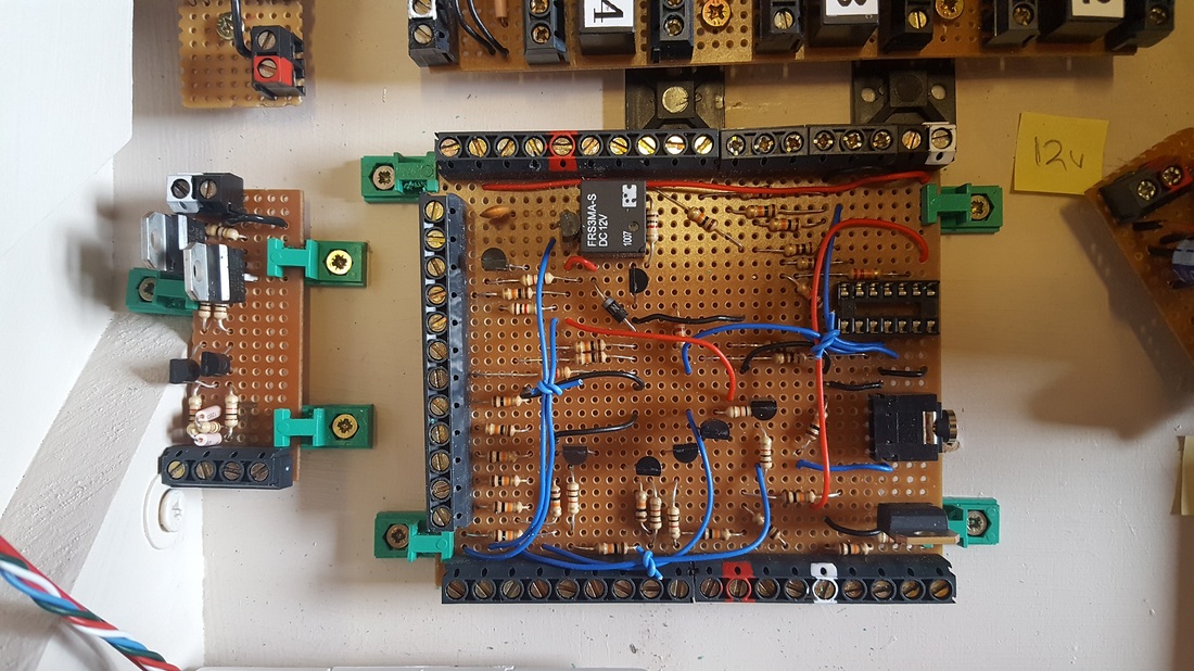
|
Upgrades
While sitting here typing away, I have been thinking of 'additions'.
Webcam. Yes, that would be a handy feature. I may either add a Network camera, or use a mini camera with a wireless AV link. Auto-dialler. You can get GSM auto-diallers very cheap on Ebay. I could add one to the alarms menu so it calls you with any issue it is having. This is actually not a bad idea, as I always have my phone with me and its better than screaming the house down with some loud alarm sounder. Fire extinguisher. I plan to 'pipe' the powder from a 30cm fire extinguisher up and out to the print bed. I will operate the extinguisher with some sort of geared handle compression rig (yet to be designed). 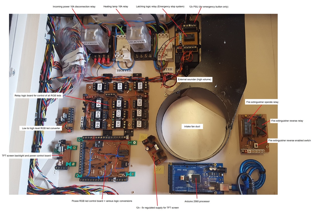

I used screw connections on all the PCB's. This makes wiring a lot easier and also adjustable.
These were all free, as I salvaged them from some old circuit boards. They make the boards bigger, but I have the space. I usually paint the tops of the terminals to aid basic identification. Red=+12v and White=+5v. Doesn't matter how tidy you try to keep these projects, they always seem to end up a mass of cables at the end (well, my projects do anyway). |
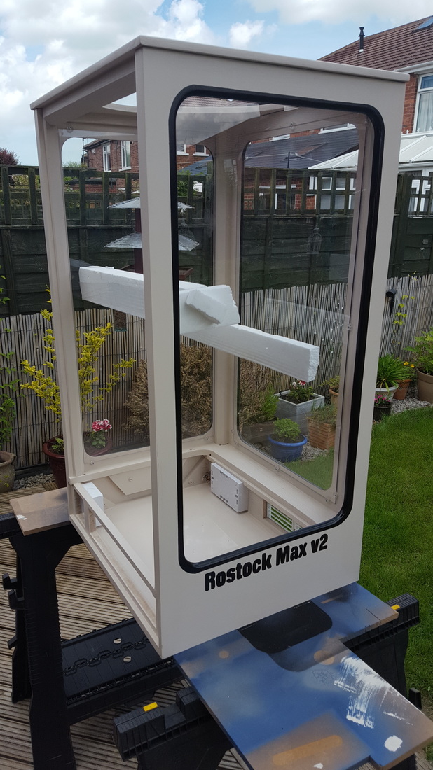
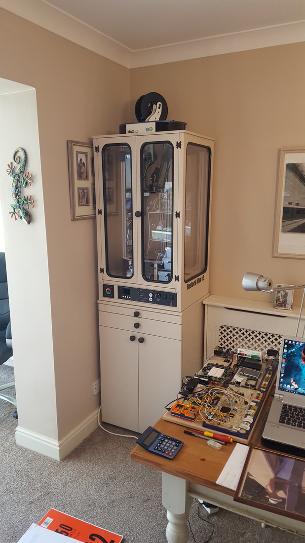
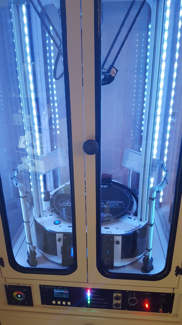
The finished (well nearly) cabinet.
|
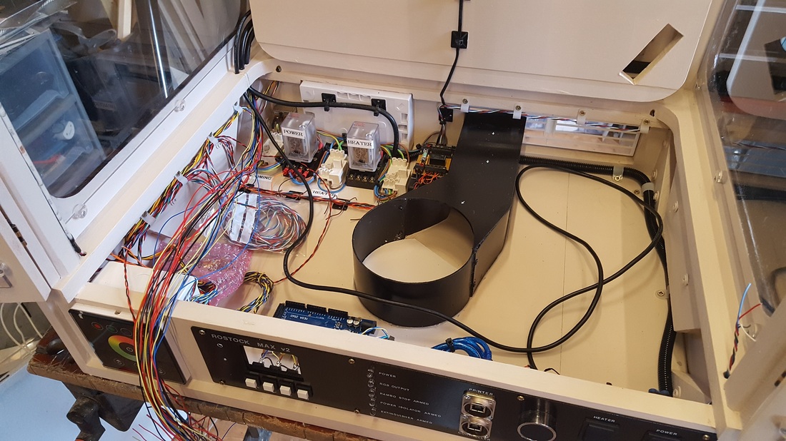
The unit is now together and I am very pleased with its performance.
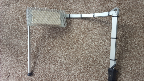
I tracked down some very nice 500w ceramic heater modules that had quite a small footprint. Good old Radio Spares had them delivered to me within 24hrs. I made up some heat reflectors, a basic mesh guard and a support frame for them. Used a Euro style power plug as a method to connect them to the supply, but enables me to remove them easily. The supply cable is Buytal and shrouded in heat sleeving. Each module pulls around 2.1 amps. |
|
The internal wiring did end up being pretty complicated.
But, it is all installed and seems to be working well. I tweaked a few software settings where required.
One alteration was I now sample the thermistors 10 times, then average them out for a steady result. They are so sensitive that the readings jump around a little otherwise. The Arduino routine is so fast anyway, you could sample them many more times and it would not be noticeable in the performance of the system.
|
|
|

|
I added a button to detect when the printer was in position, and I think I may add a sensor to the doors to switch off the 230v to the heater panels when the doors are open.
There are no visible live contacts, but its just another simple safety feature. I can add an input to the Arduino pretty easily and simply program it to turn off the heater relay if the switch is operated. I will add the fire extinguisher system later. The electronics are all in place, I just need to add the actual powder unit. The next addition is a wireless camera on the hotend rig. |
|
|
|
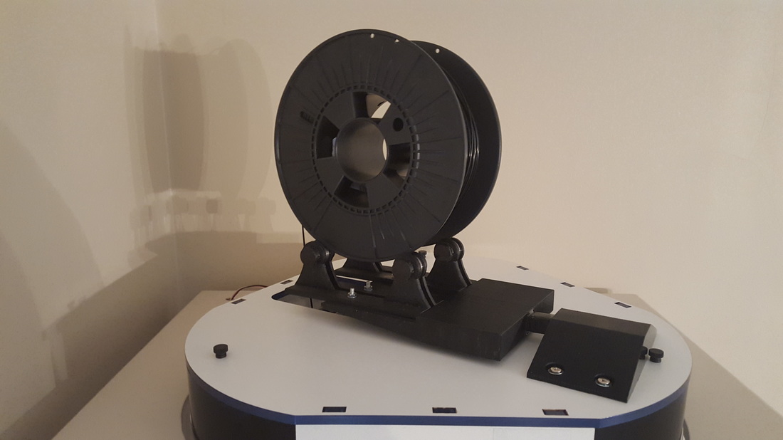
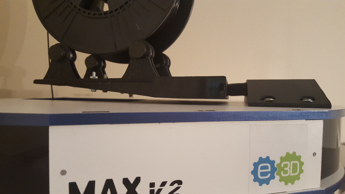
New filament spool holder
|
Finally got around to building (well printing) a new filament spool holder. The original one that comes with the RoStock Max V2 kit is basically a stick. And a square stick at that. So the filament does this really annoying thump thing as the round spool tries to rotate around the square stick as it pays out filament. The new spool holder has 4x enclosed bearings for smoother running, and the roll basically just sits on top of them. They can be moved in and out, depending on the width of the filament roll. The entire roller unit is suspended on a 5kg load cell. This enables me to weigh the filament roll and get a vague idea of how much filament I am using. The printer control panel does tell you how much filament you are taking off the reel during printing, but this weight method gives me a very good idea of how much is left on the spool. The weight sensor (load cell) goes through a HX711 conversion module that gives me a reading I can sample with a Picaxe 08m2 chip. This Picaxe 8 pin IC samples the HX711 fifty times before taking an average and sending that result down to the main Arduino cabinet controller in the form of a 0-4v signal. The 08m2 is basically doing this task to save the Arduino doing it. The same line to the Arduino controller is also used to indicate that the printer has hit the top stop microswitches. This turns off the heater (if its on). This is a 5v signal to the Arduino (hence the load cell signal only uses 0-4v). |
|