The world of Arduino's
|
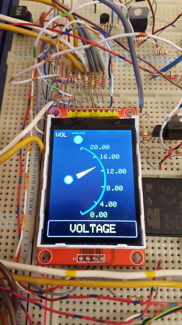
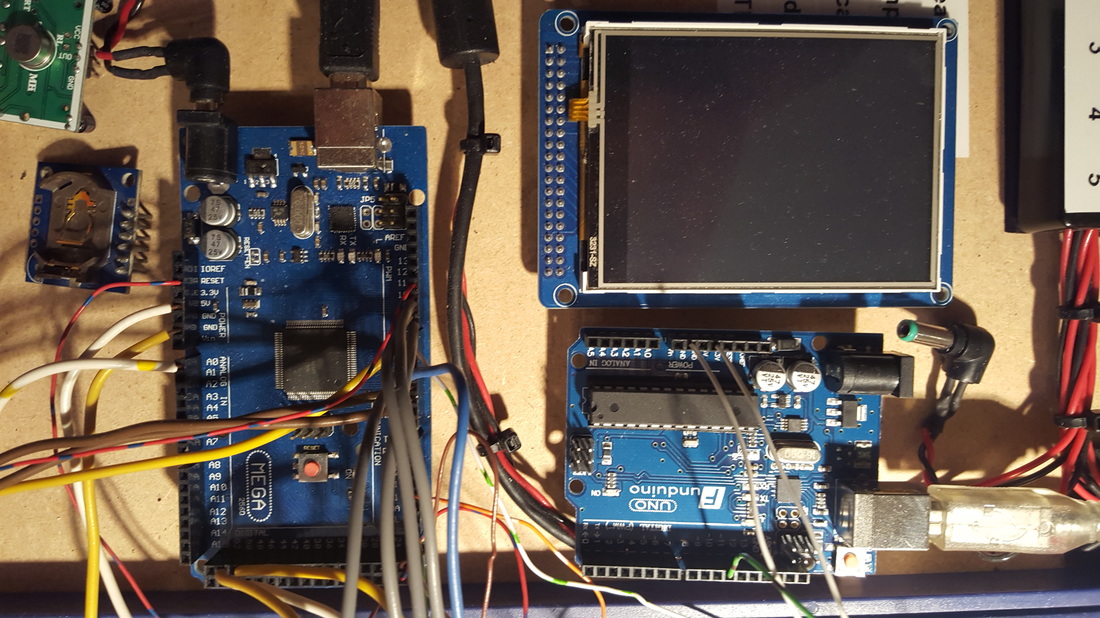
Arduino. Been around forever it seems. Many years back, I wanted some digital gauges for my pickup truck, so I decided to learn the Arduino programming system. I purchased a selection of cheap LCD screens off of Ebay and away we went. They are different from the Picaxe chips, in that you upload library's of commands and add them to your coding. You can call upon the pre-programmed commands in the library and therefore obtain the desired result a lot quicker. The hard work is done behind the scenes for you and saves you hours of programming. As an example of this, the graphics are drawn on my gauges using a pre-loaded set of commands. I simply ask it to draw a circle, or a line, or a box. You give it the colour, the co-ords and it does the rest. It still takes some lengthy programming to get the results you want, but nowhere near what it could have taken. To the right here you see my Arduino corner on my prototyping board. I have an Arduino UNO (left) and and a Mega 2560 (right). The Mega is the most powerful one and has a wealth of abilities that I will not go into here. I do find that my projects nearly always 'fill up' the smaller processors like the Pro-mini's and the UNO. I always seem to end up back with a 2560p. |
|
|
|
Again, these processors are programmed using the free software on the web. Arduino's are VERY popular, and there is a mountain of available data for them. If you can think of a project, its highly likely that somewhere on the internet, a program has already been written that will accomplish 80% of what you need. So before spending hours trying to do something yourself, have a search for somthing similar. |
You can also buy a multitude of 'shields'. These are boards that plug into the top of your Arduino board and give it extra functions.
The UNO and Mega boards have rows of header sockets along the tops that allow these boards to 'stack' on top.
The carry the essential supplies up through the boards and allow you to make very complex systems.
The UNO and Mega boards have rows of header sockets along the tops that allow these boards to 'stack' on top.
The carry the essential supplies up through the boards and allow you to make very complex systems.
|
These shields can be motor drivers, sensors, GPS modules, radio modules, MP3 modules.... you name it.
You can also buy blank shields to make your own systems on. I also have a few Mini Pro boards. These are great little devices and I used one to make the gear indicator for my truck. The Arduino Pro Mini is a microcontroller board based on the ATmega328. It has 14 digital input/output pins (of which 6 can be used as PWM outputs), 6 analog inputs, an on-board resonator, and a reset button. The ATmega328 has 32 kB of flash memory for storing code (of which 0.5kB is used for the bootloader). It has 2 kB of SRAM and 1kBs of EEPROM |
If you want to read up on these devices, then a quick Google will return a huge amount of results. |
Arduino's and TFT touchscreens
|
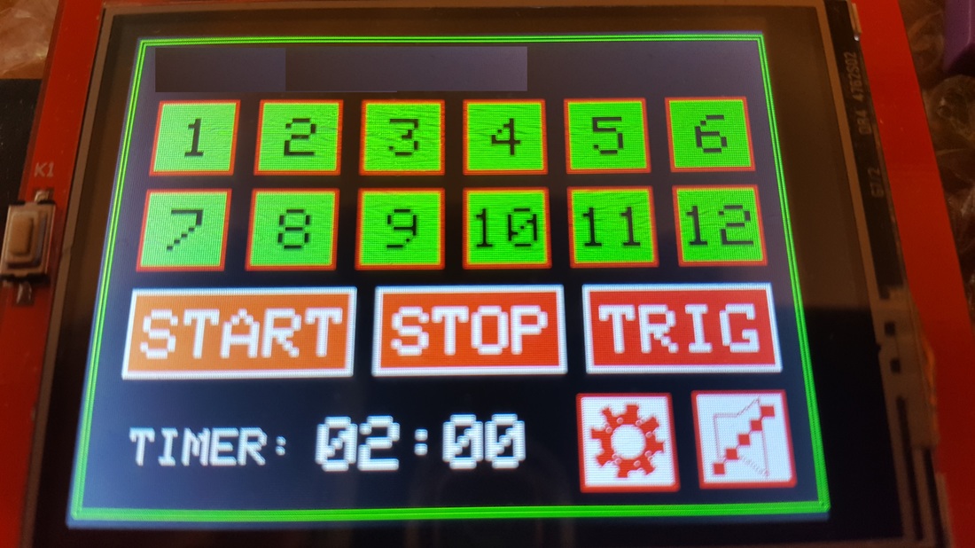
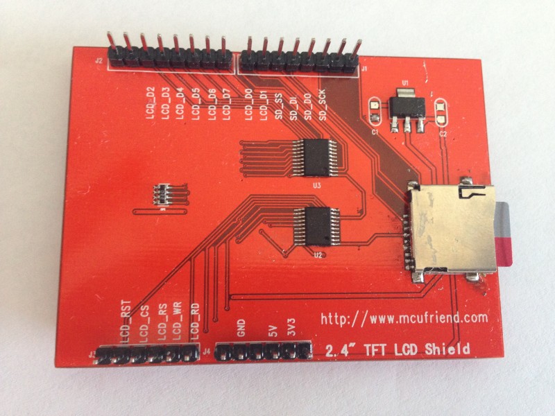
Well I purchased a 2.4" touch screen on Ebay and thought I would have a go at building a timer module (for a friend - hence their name obscured at the top of the TFT screen).
The screen came as a package with an Arduino Uno. The screen shield plugged directly into the Uno and it didn't take too long to get the screen up and running. However, it does have a few drawbacks. The screen pretty much uses up all the inputs and output pins. This leaves you only a few (4 in this case) to use as actual control lines to whatever you are controlling. 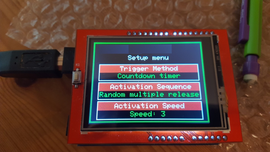
The better option would be to use an Arduino 2560 mega. Far more input/output pins and only a few pounds more in price than the Uno. It also has the advantage of having a much larger memory. I have almost filled the program memory of the Uno, and that is after sacrificing the SD card reader feature on the screen (which is handy for loading local graphics). That library uses far too much memory. If I use the Mega, then I can re-instate the handy SD card reader. |
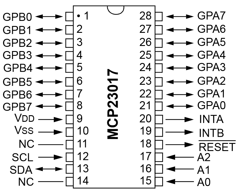
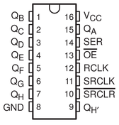
Now I have come up with a few ways around this issue. I could add a few MCP230017 I/O expander chips . A pair of these SPI controlled chips would allow me to control 16 extra inputs/outputs. They also do this IC with I2c control, but I have SPI lines available, so I will use those. There is also the 74HC595 Shift register IC. That again could give me more pins (8 per chip). They do a higher current versions too, but I think the above will be fine. The only problem is really, you are making it more complicated than it really needs to be (plus a bigger PCB footprint)
|

|
But, as usual... its not that simple. Yes, the TFT screen will plug into the Mega2560, but it does not work.
The port pins on the Mega are different, and so it does not work unless you twiddle around with it. I found several reference pages on the internet for using a Mega with this screen, but they used a library that shifted the ports to make it work. This leads to a speed reduction of 30 or 40%. That isn't really acceptable. |
The Arduino forum
My initial investigations lead me to the Arduino forum
Hmm. I found out pretty quickly that any dull, boring question that they are not interested in quickly leads to a snarky, short tempered answer from the big-headed knowledgable bods who don't have time for newbies.
Sometimes you are just better off working it out for yourself.
I thought, forums were supposed to be helpful and guide for the newbies. The Arduino forum proved the exception to that rule.
Unless you are a top level programmer, you will highly likely just get sarcastic, unhelpful crap, rather than the help you were looking for.
Someone will probably eventually step in, but the majority of the time, you are better off out of there.
'So why didn't you write the result into an array and then write a function to convert your data'.
If I knew how to do it, I wouldn't be in here.
The other ones are, 'So why do you want to do that?', or 'I don't see why you would want to do that'. NOT the question.
I think I am on about my 15th Arduino forum user name (bounced through a VPN). I usually either rage quit the thread (and the forum), or say what I think of these guys and get banned.
Not everyone in there is bad. Some people will come to your aid and there are some very helpful guys. It's just finding them.
You will nearly always need to show some kind of wiring diagram, photo of your wiring and probably your code.
Not doing the above is frowned upon, even if it's actually not relevant to your question.
My advice? Look around on Google, you can work out nearly all issues with a little bit of detective work.
The Arduino forum CAN BE a nasty little place sometimes.
|
Anyway, I breadboarded the screen and began playing around.
Few hours later and we are sorted. SD card, touchscreen all functioning. The connections for the rear of the 2.4" touchscreen are shown here on the right. I used the Adafruit_GFX.h graphics library, and the Adafruit_TFTLCD.h screen library. You also need the TouchScreen.h and SD.h libraries if you want to use the touchscreen and SD card slot. For those that are interested, the final connections to the Mega are listed below. |
|
Arduino code and connections
|
If you measure the resistance between the A2 pin and pin 8 (low ohms range), you can add that reading into the touchscreen line to the right here and obtain a more accurate touchscreen result. This code and set of connections enabled me to get the screen fully working without altering the content any of the library files. Links to the libraries below, but you can also find them by searching the libraries in the IDE (Programming software). |
-------------------------------------------------------- Make sure your SD card images are saved as 320x240 pixels and as BMP files. Screen Mega2560 3.3v 3.3v 5v 5V GND GND LCD_RD A0 LCD_WR A1 LCD_RS A2 LCD_CS A3 LCD_RST A4 LCD_D0 22 LCD_D1 23 LCD_D2 24 LCD_D3 25 LCD_D4 26 LCD_D5 27 LCD_D6 28 LCD_D7 29 SD_SS 53 SD_D1 51 SD_D0 50 SD_SCK 52 |
//2.4" Touchscreen to Arduino Mega2560
#include <Adafruit_GFX.h> // Core graphics library
#include <Adafruit_TFTLCD.h> // Hardware-specific library
#include <TouchScreen.h> //Touchscreen library
#include <SD.h> //SD card library
#include <SPI.h> //SPI comms library (Serial Peripheral Interface)
#define LCD_CS A3 // Chip Select goes to Analog 3
#define LCD_CD A2 // Command/Data goes to Analog 2
#define LCD_WR A1 // LCD Write goes to Analog 1
#define LCD_RD A0 // LCD Read goes to Analog 0
#define LCD_RESET A4
#define SD_CS 53
#define BUFFPIXEL 70 //Buffer for the SD card image reader
Adafruit_TFTLCD tft(LCD_CS, LCD_CD, LCD_WR, LCD_RD, LCD_RESET);
#define YP A3 // must be an analog pin
#define XM A2 // must be an analog pin
#define YM 23 // can be a digital pin
#define XP 22 // can be a digital pin
#define TS_MINX 150
#define TS_MINY 120
#define TS_MAXX 920
#define TS_MAXY 940
#define sdcard 52
TouchScreen ts = TouchScreen(XP, YP, XM, YM, 306); //306 is the ohms reading between pins A2 and 8 (X axis).
//------------------------------------------------------------------------------------------------------------------------------------
void setup(void) {
tft.reset();
uint16_t identifier = 0x9341; //The graphics chip on my screen (yours may differ)
tft.begin(identifier);
tft.setRotation(3); //Sets the rotation of the display
Serial.print(F("Initializing SD card..."));
if (!SD.begin(SD_CS)) {
Serial.println(F("failed!"));
//return;
}
Serial.println(F("OK!"));
bmpDraw("Testimage.bmp", 0, 0); //The name of the image you wish to display
delay(2000);
#define MINPRESSURE 10 //Set the touchscreen pressures
#define MAXPRESSURE 1000
}
//------------------------------------------------------------------------------------------------------------------------------------
void loop(void) {
digitalWrite(52, HIGH);
TSPoint p = ts.getPoint();
digitalWrite(52, LOW);
pinMode(XM, OUTPUT);
pinMode(YP, OUTPUT);
if (p.z > MINPRESSURE && p.z < MAXPRESSURE) { //If the screen detects a press, then read the co-ords and check for button presses
Serial.print("X = "); Serial.print(p.x); //Display the X co-ordinate in the serial monitor
Serial.print("\tY = "); Serial.print(p.y); //Display the Y co-ordinate in the serial monitor
Serial.print("\tPressure = "); Serial.println(p.z); //Display the screen touch pressure in the serial monitor
//This is the loop you put your screen detection co-ords inside.
}
//----------------------------------------------------------------------
void bmpDraw(char *filename, int x, int y) {
File bmpFile;
int bmpWidth, bmpHeight; // W+H in pixels
uint8_t bmpDepth; // Bit depth (currently must be 24)
uint32_t bmpImageoffset; // Start of image data in file
uint32_t rowSize; // Not always = bmpWidth; may have padding
uint8_t sdbuffer[3*BUFFPIXEL]; // pixel in buffer (R+G+B per pixel)
uint16_t lcdbuffer[BUFFPIXEL]; // pixel out buffer (16-bit per pixel)
uint8_t buffidx = sizeof(sdbuffer); // Current position in sdbuffer
boolean goodBmp = false; // Set to true on valid header parse
boolean flip = true; // BMP is stored bottom-to-top
int w, h, row, col;
uint8_t r, g, b;
uint32_t pos = 0, startTime = millis();
uint8_t lcdidx = 0;
boolean first = true;
if((x >= tft.width()) || (y >= tft.height())) return;
Serial.println();
Serial.print(F("Loading image '"));
Serial.print(filename);
Serial.println('\'');
// Open requested file on SD card
if ((bmpFile = SD.open(filename)) == NULL) {
Serial.println(F("File not found"));
return;
}
// Parse BMP header
if(read16(bmpFile) == 0x4D42) { // BMP signature
Serial.println(F("File size: ")); Serial.println(read32(bmpFile));
(void)read32(bmpFile); // Read & ignore creator bytes
bmpImageoffset = read32(bmpFile); // Start of image data
Serial.print(F("Image Offset: ")); Serial.println(bmpImageoffset, DEC);
// Read DIB header
Serial.print(F("Header size: ")); Serial.println(read32(bmpFile));
bmpWidth = read32(bmpFile);
bmpHeight = read32(bmpFile);
if(read16(bmpFile) == 1) { // # planes -- must be '1'
bmpDepth = read16(bmpFile); // bits per pixel
Serial.print(F("Bit Depth: ")); Serial.println(bmpDepth);
if((bmpDepth == 24) && (read32(bmpFile) == 0)) { // 0 = uncompressed
goodBmp = true; // Supported BMP format -- proceed!
Serial.print(F("Image size: "));
Serial.print(bmpWidth);
Serial.print('x');
Serial.println(bmpHeight);
// BMP rows are padded (if needed) to 4-byte boundary
rowSize = (bmpWidth * 3 + 3) & ~3;
if(bmpHeight < 0) {
bmpHeight = -bmpHeight;
flip = false;
}
// Crop area to be loaded
w = bmpWidth;
h = bmpHeight;
if((x+w-1) >= tft.width()) w = tft.width() - x;
if((y+h-1) >= tft.height()) h = tft.height() - y;
// Set TFT address window to clipped image bounds
tft.setAddrWindow(x, y, x+w-1, y+h-1);
for (row=0; row<h; row++) { // For each scanline...
if(flip) // Bitmap is stored bottom-to-top order (normal BMP)
pos = bmpImageoffset + (bmpHeight - 1 - row) * rowSize;
else // Bitmap is stored top-to-bottom
pos = bmpImageoffset + row * rowSize;
if(bmpFile.position() != pos) { // Need seek?
bmpFile.seek(pos);
buffidx = sizeof(sdbuffer); // Force buffer reload
}
for (col=0; col<w; col++) { // For each column...
// Time to read more pixel data?
if (buffidx >= sizeof(sdbuffer)) { // Indeed
// Push LCD buffer to the display first
if(lcdidx > 0) {
tft.pushColors(lcdbuffer, lcdidx, first);
lcdidx = 0;
first = false;
}
bmpFile.read(sdbuffer, sizeof(sdbuffer));
buffidx = 0; // Set index to beginning
}
// Convert pixel from BMP to TFT format
b = sdbuffer[buffidx++];
g = sdbuffer[buffidx++];
r = sdbuffer[buffidx++];
lcdbuffer[lcdidx++] = tft.color565(r,g,b);
} // end pixel
} // end scanline
// Write any remaining data to LCD
if(lcdidx > 0) {
tft.pushColors(lcdbuffer, lcdidx, first);
}
Serial.print(F("Loaded in "));
Serial.print(millis() - startTime);
Serial.println(" ms");
} // end goodBmp
}
}
bmpFile.close();
if(!goodBmp) Serial.println(F("BMP format not recognized."));
}
uint16_t read16(File f) {
uint16_t result;
((uint8_t *)&result)[0] = f.read(); // LSB
((uint8_t *)&result)[1] = f.read(); // MSB
return result;
}
uint32_t read32(File f) {
uint32_t result;
((uint8_t *)&result)[0] = f.read(); // LSB
((uint8_t *)&result)[1] = f.read();
((uint8_t *)&result)[2] = f.read();
((uint8_t *)&result)[3] = f.read(); // MSB
return result;
}